* Look Inside Your Potentiometer
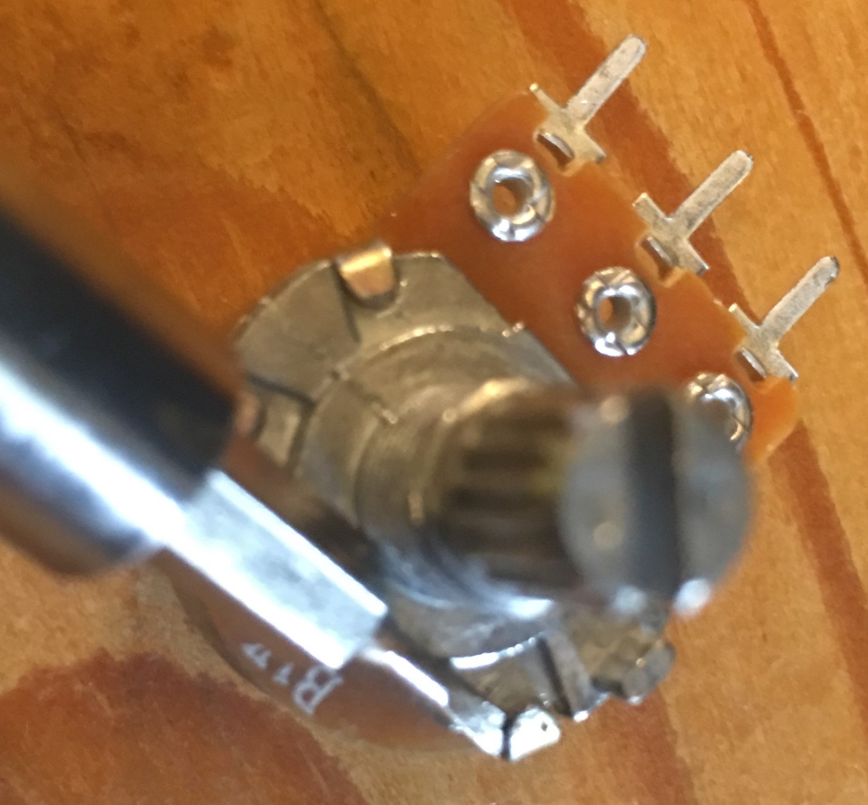
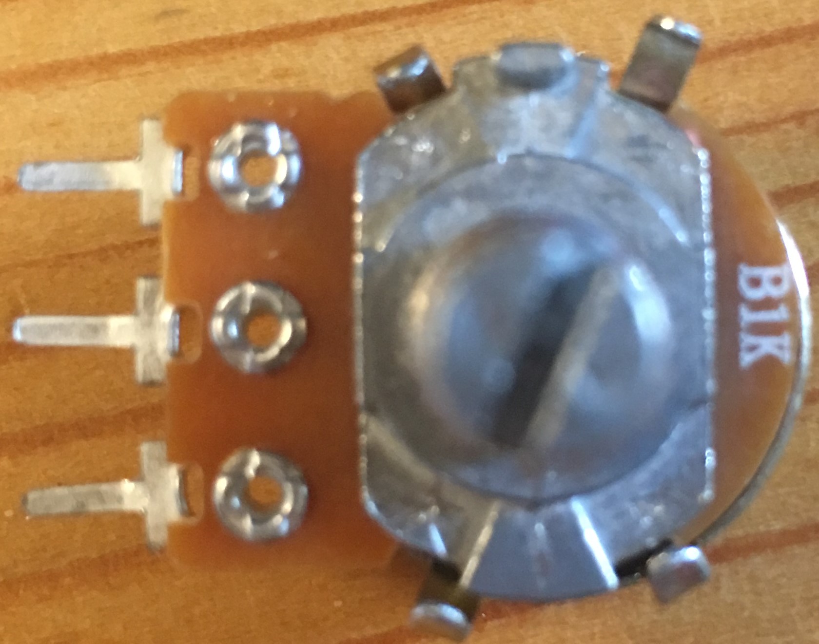
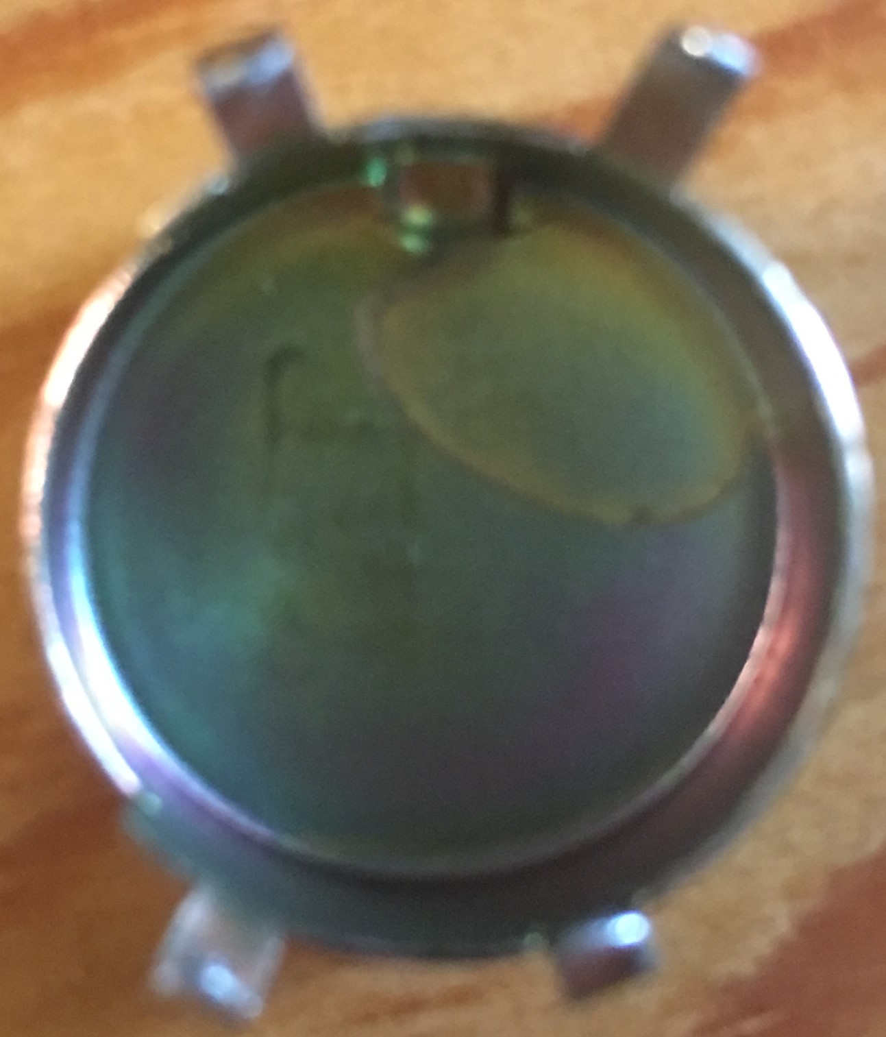
Here are some photos from different angles of the potentiometer I used (before prying it open):

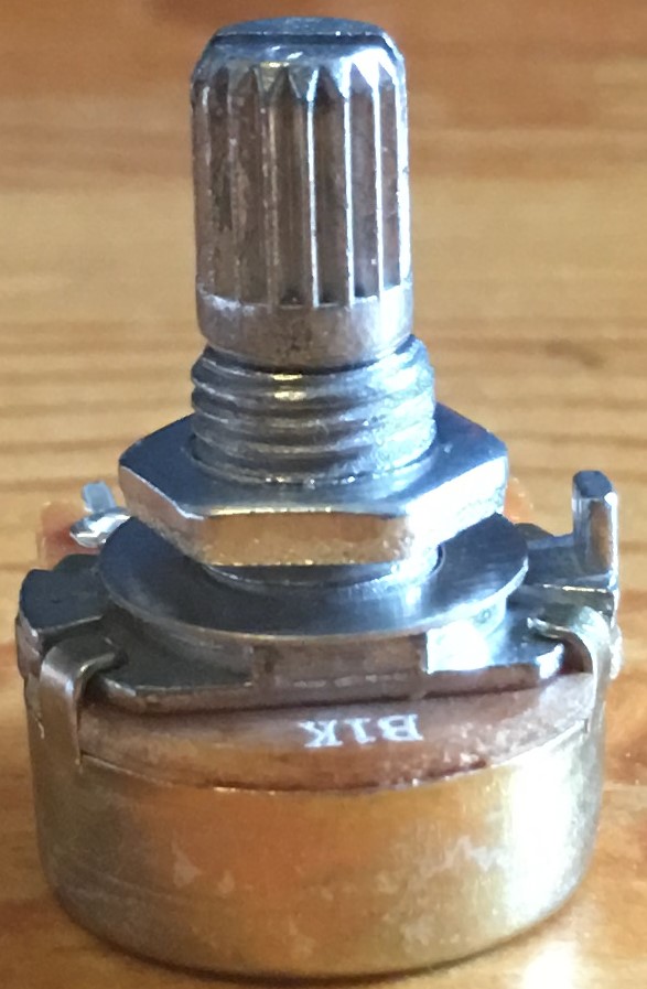
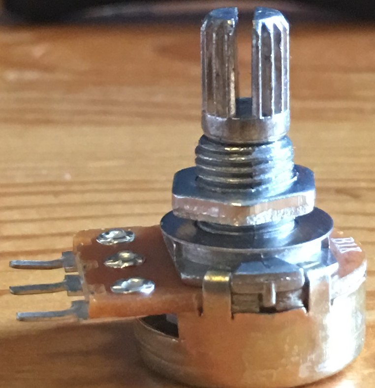

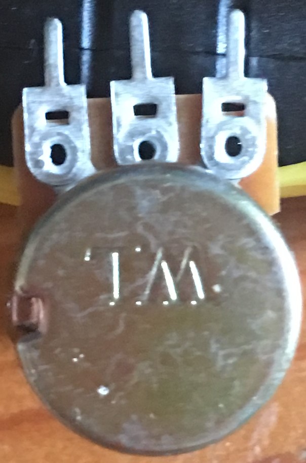

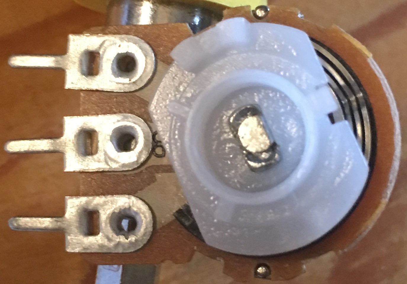
Time to open it up!
* Testing the Potentiometer
|
Middle and Right terminals |
Resistance |
| Min. Resistance (shaft fully turned clockwise) |
2Ω |
| Max. Resistance (shaft fully turned counterclockwise) |
1.036KΩ |
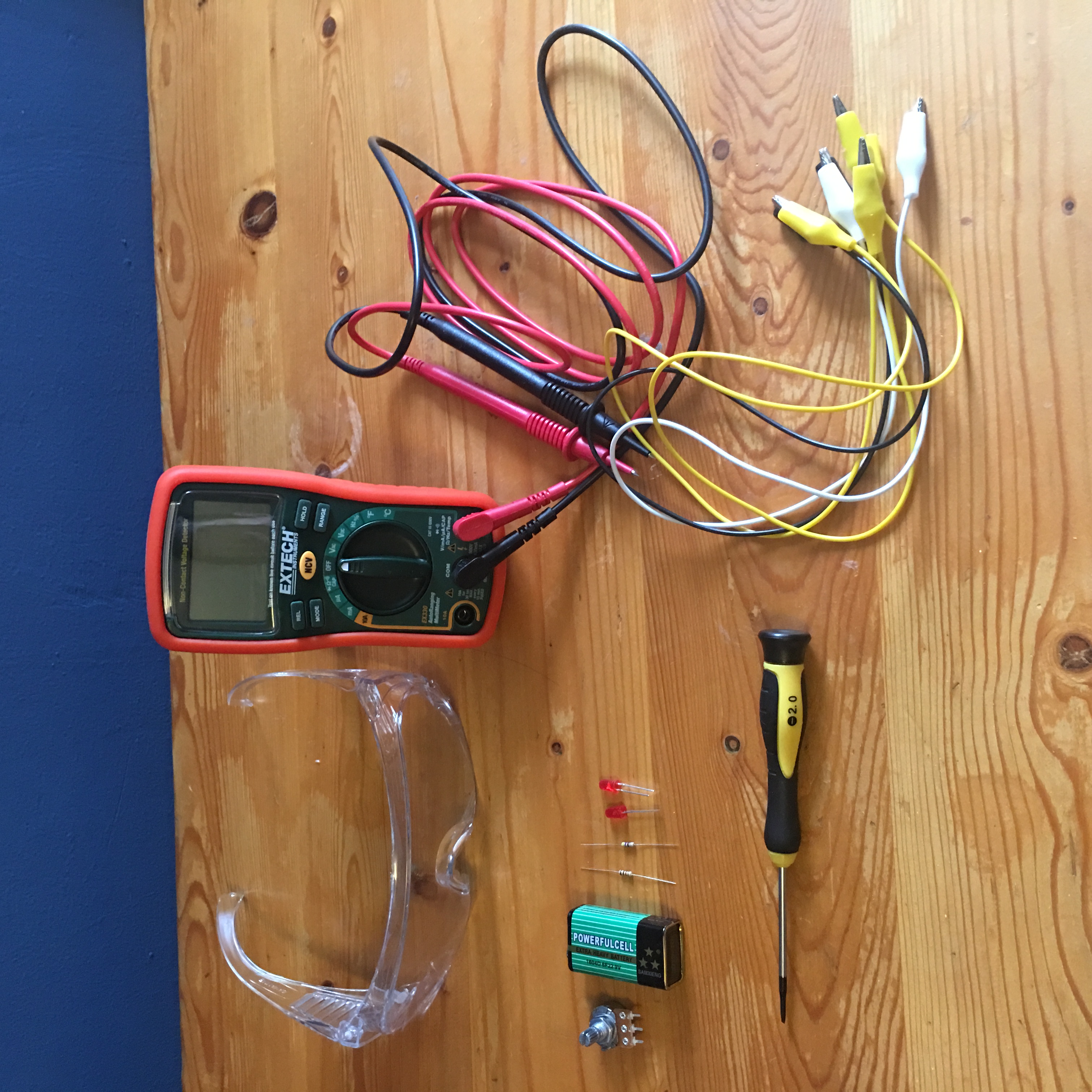
* Dimming Your LED
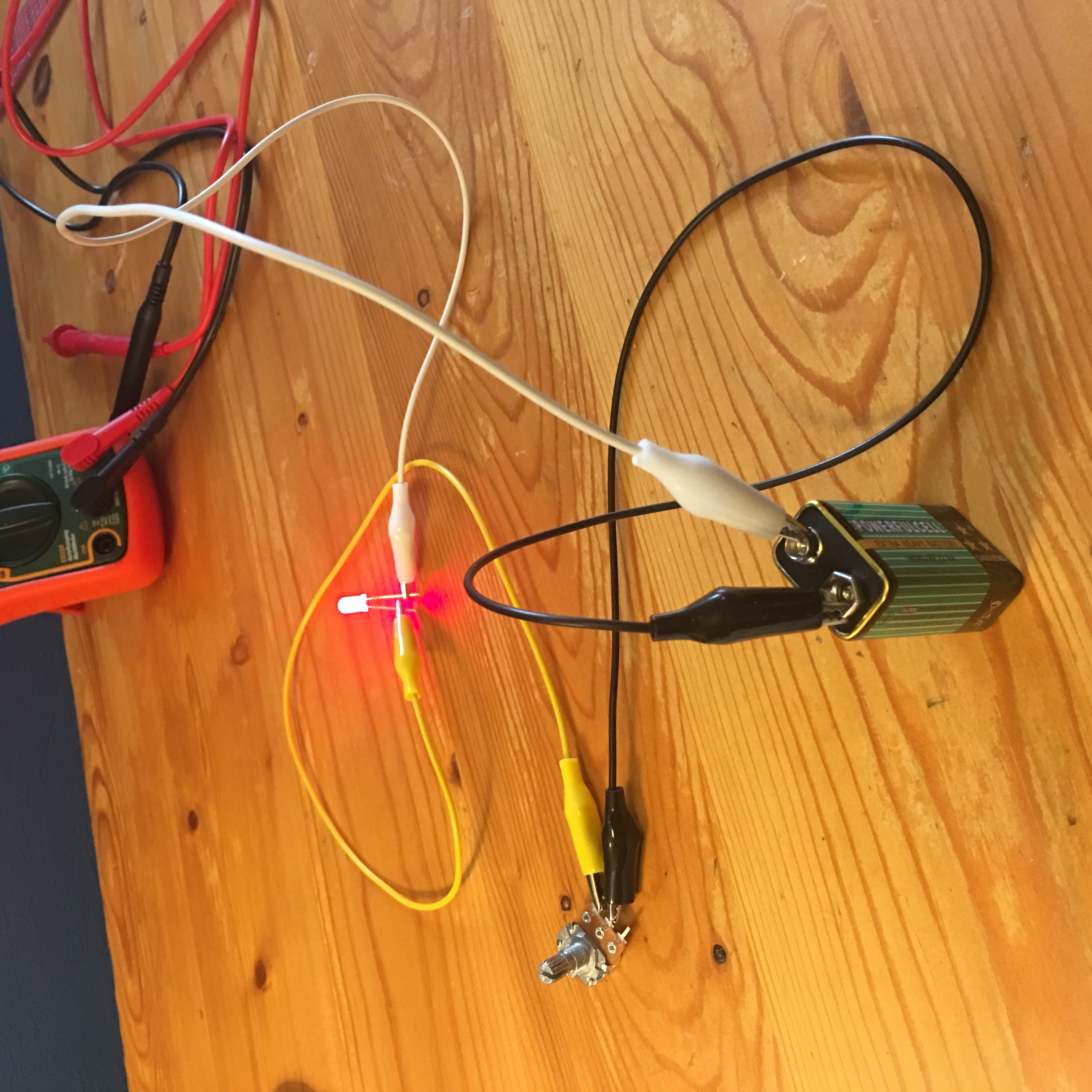
The LED that wouldn’t die
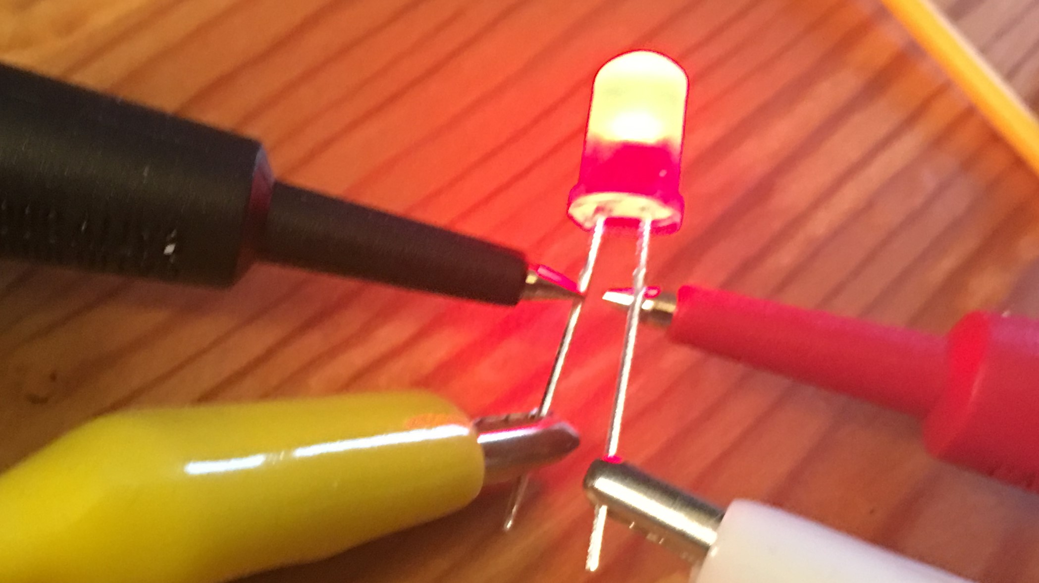
I did NOT manage to burn the LED. I even connected it directly to the 9V battery but it just refused to burn.
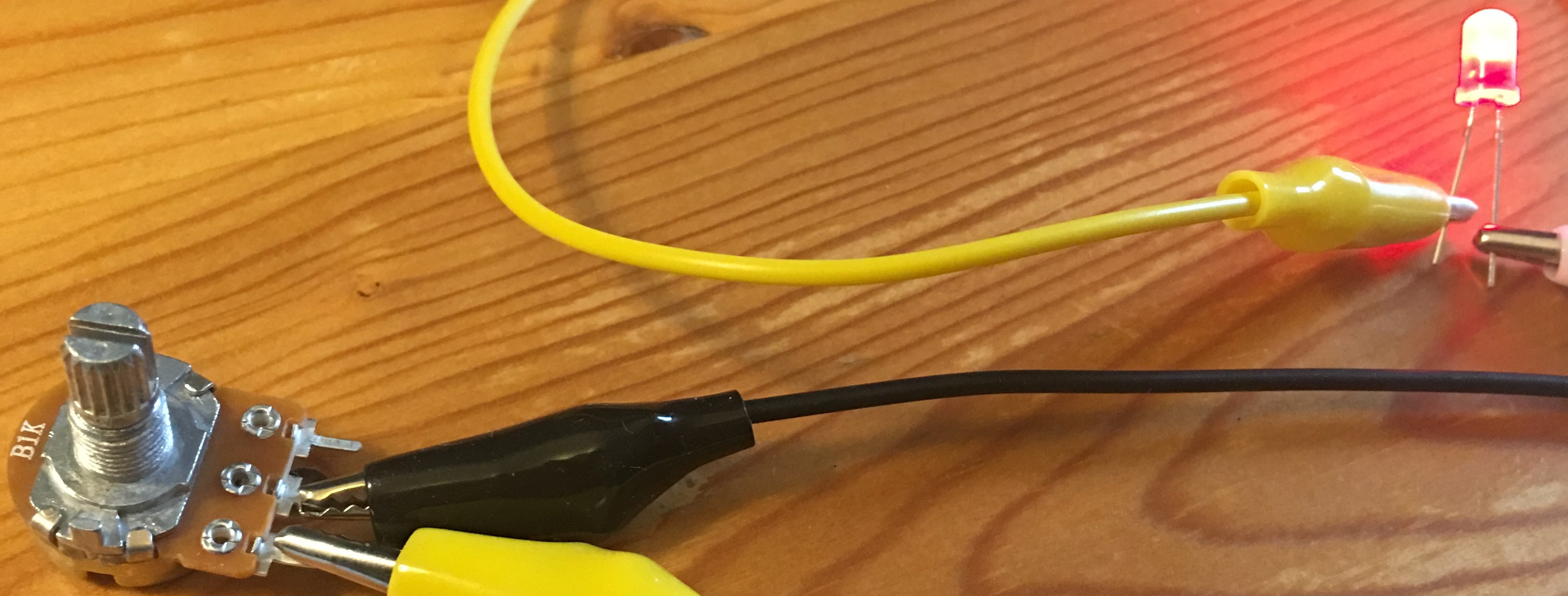
Still, it was fun to play with the potentiometer, turning the knob and watching the LED’s brightness change as less and more current goes through it. A potentiometer isn’t polar so the LED would light up no matter which test lead was connected to which of the potentiometer’s terminals.
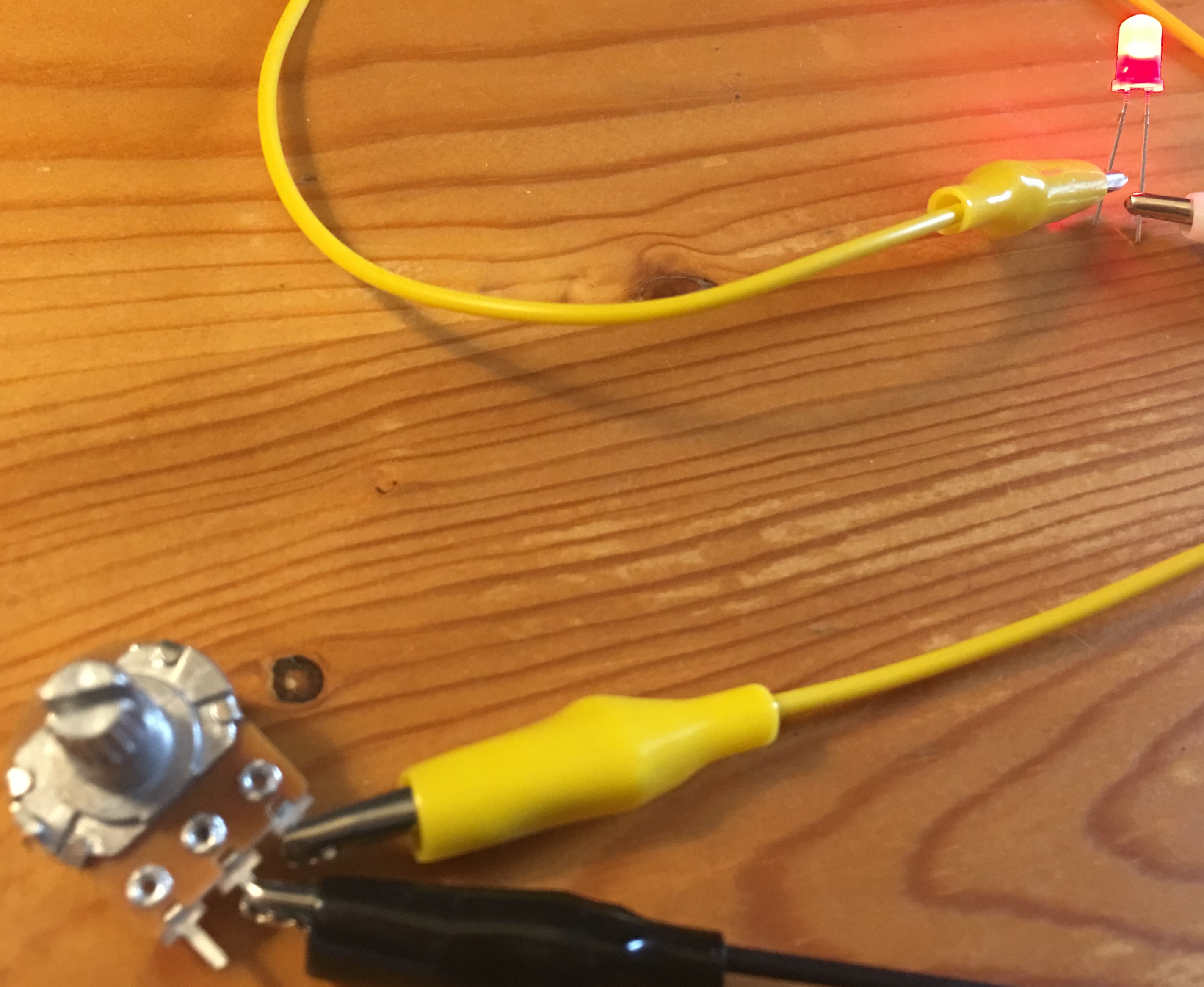
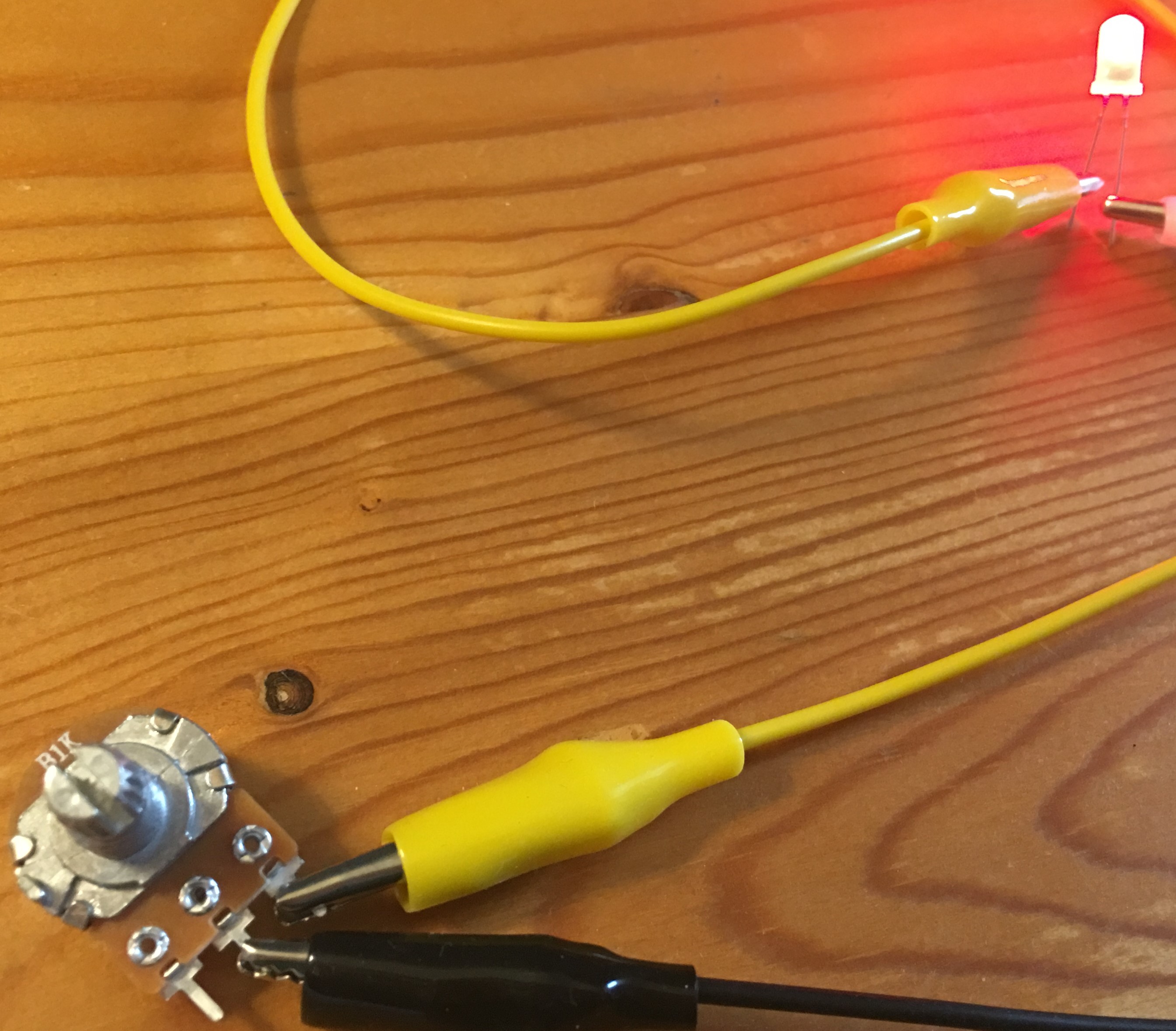
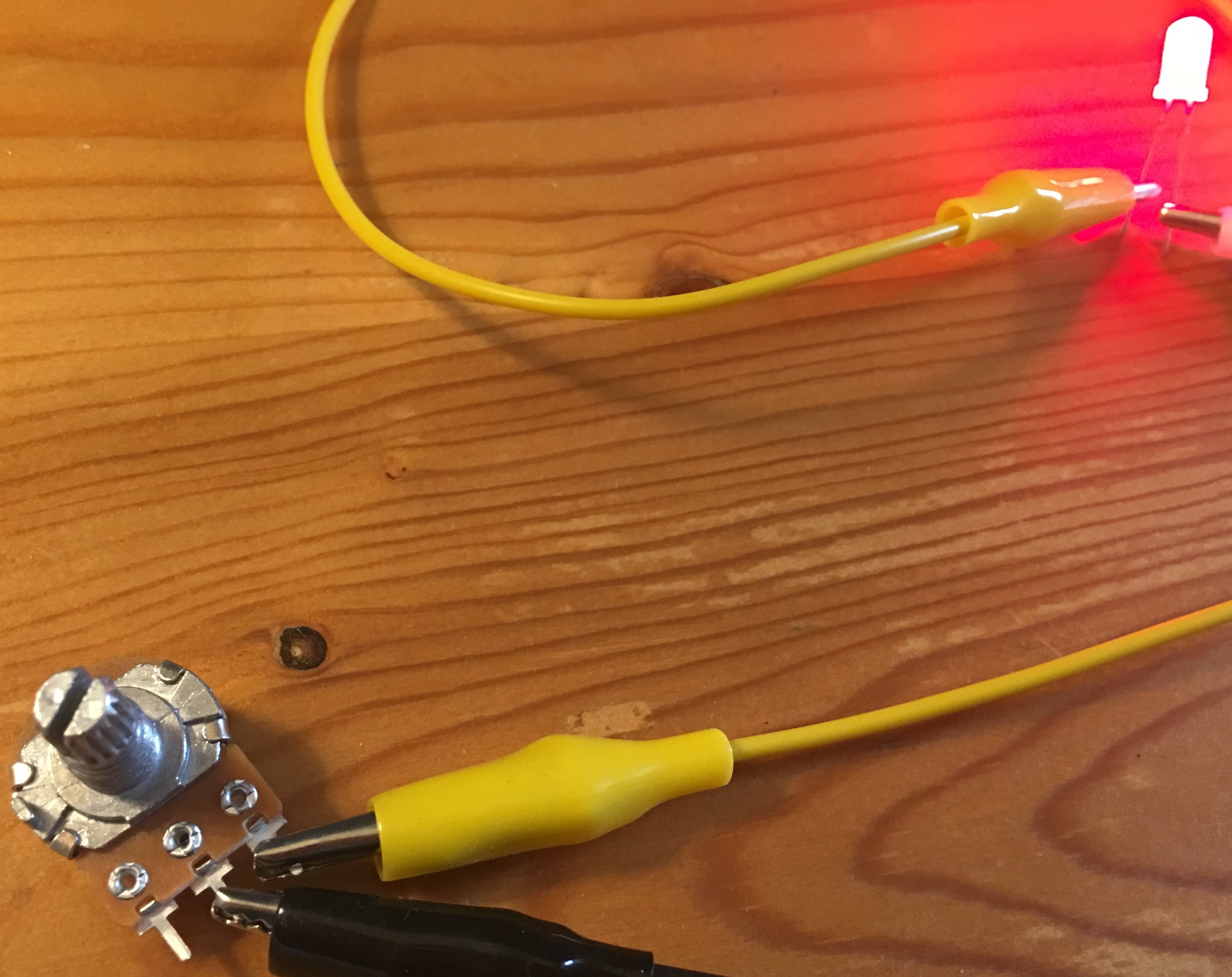
Center and Right terminals. As you turn the shaft clockwise, the LED shines brighter.

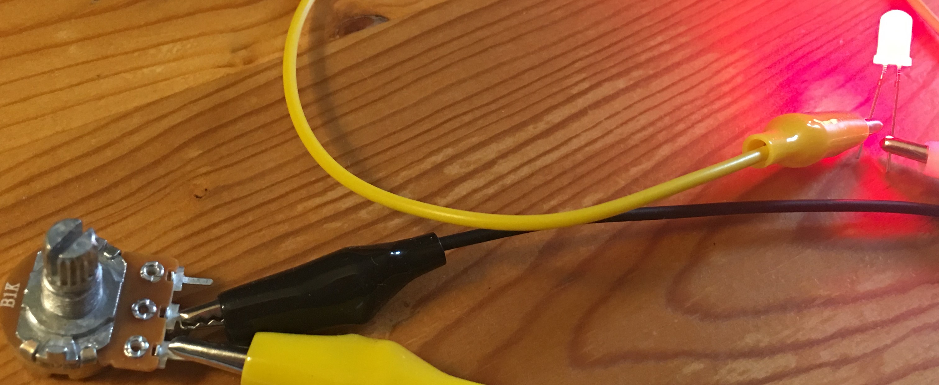
Center and Left terminals. As you turn the shaft counterclockwise, the LED shines brighter.
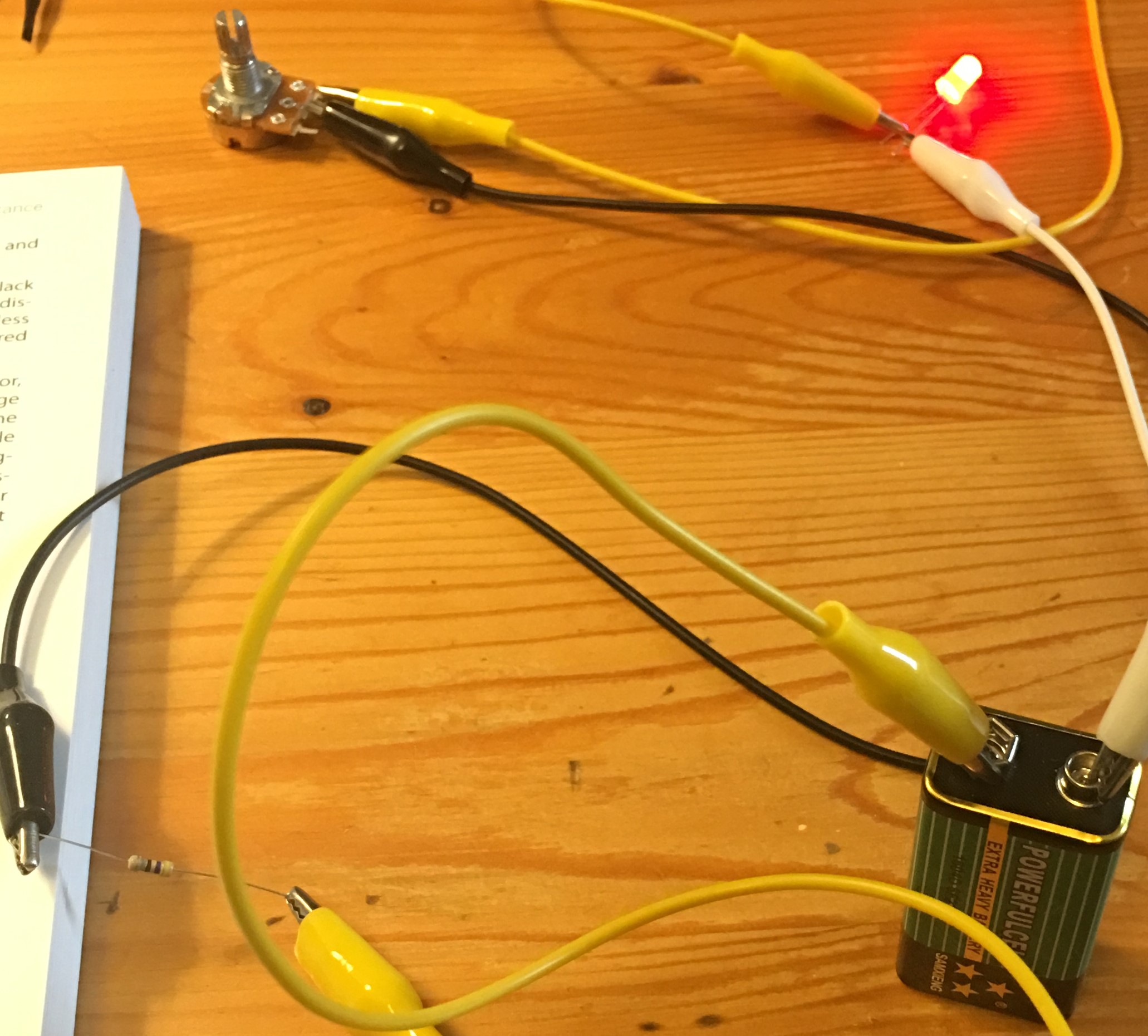
Protecting the LED with a resistor
* Measuring Potential Difference

|
Middle and Right terminals |
Voltage 470Ω resistor |
Voltage 1KΩ resistor |
|
Min. Resistance (shaft fully turned clockwise) |
24.4mV |
13.5mV |
|
Max. Resistance (shaft fully turned counterclockwise) |
4.57V |
3.530V |

Measuring potential difference across an LED and a resistor
|
Middle and Right terminals |
LED |
470Ω resistor |
|
Min. Resistance (shaft fully turned clockwise) |
2mV |
5.84V |
|
Max. Resistance (shaft fully turned counterclockwise) |
1.907V |
2.049V |
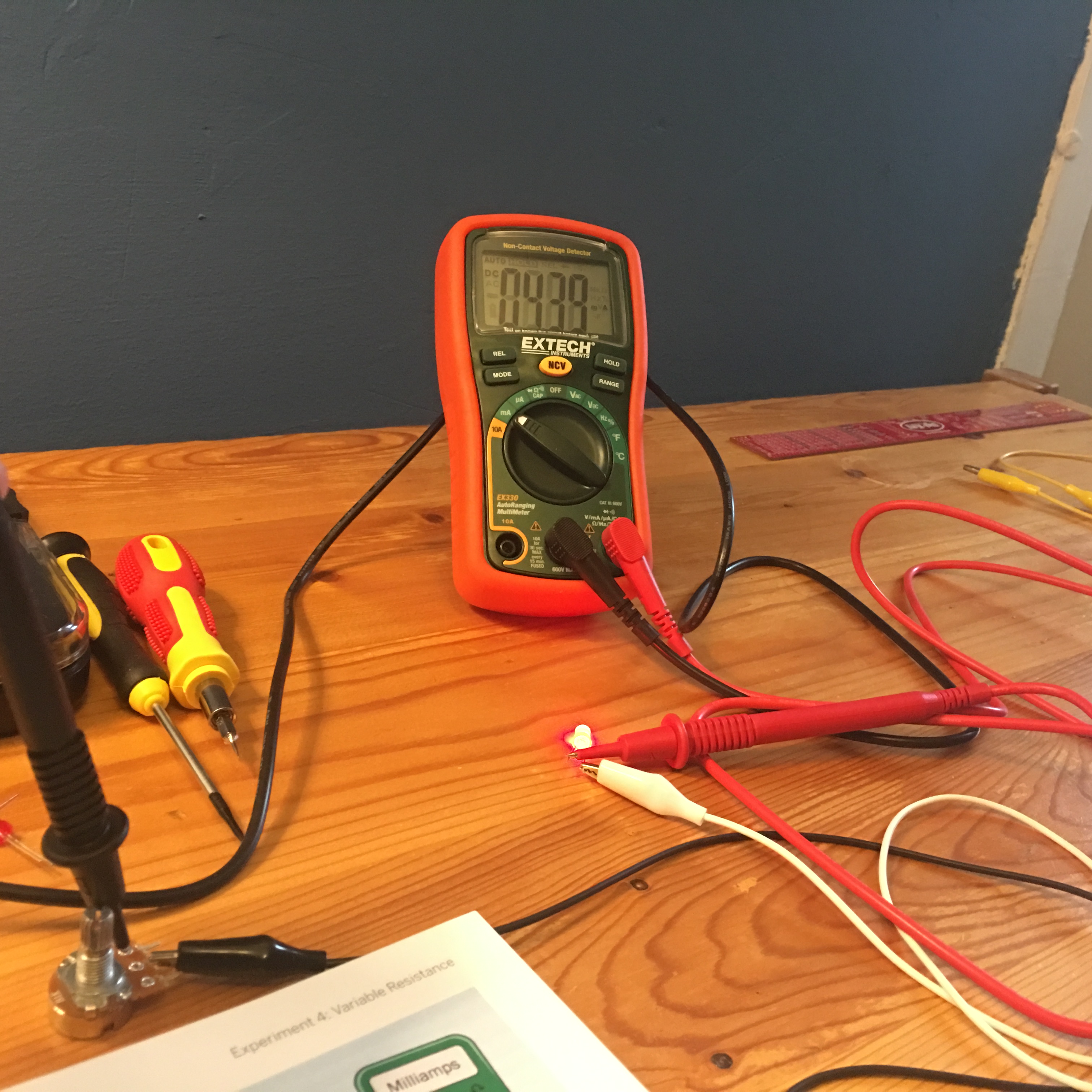
* Checking the Current
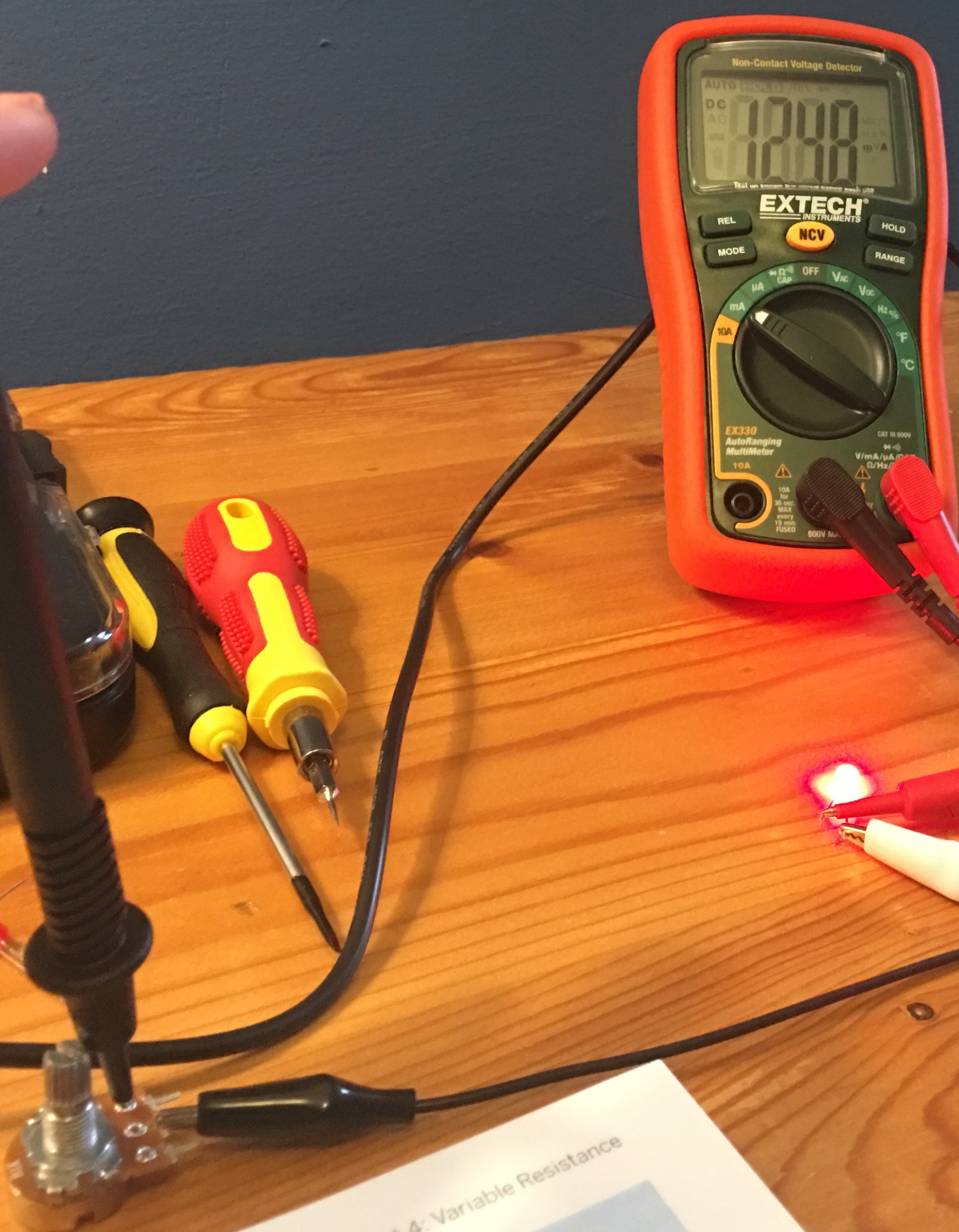
|
Multimeter between the LED and Potentiometer |
Current |
|
Min. Resistance (shaft fully turned clockwise) |
12.48mA |
|
Max. Resistance (shaft fully turned counterclockwise) |
4.39mA |
|
Multimeter between the battery and LED |
Current |
|
Min. Resistance (shaft fully turned clockwise) |
12.30mA |
|
Max. Resistance (shaft fully turned counterclockwise) |
4.32mA |
* Making Measurements
|
Multimeter between the potentiometer and battery (no LED) |
Current |
|
Min. Resistance (shaft fully turned clockwise) |
8.50 mA |
|
Medium Resistance (shaft turned halfway) |
6.33mA |
|
Max. Resistance (shaft fully turned counterclockwise) |
4.25mA |
* Fundamentals: Series and Parallel
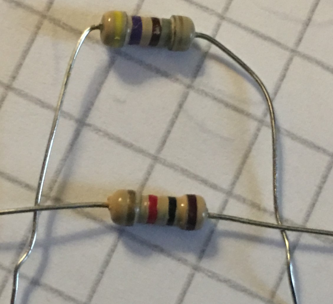
Two resistors in parallel (R1= 470Ω, R2= 1KΩ) offer an equivalent resistance of 319.73Ω
Of course, the measurements won’t always be what we expect, this due to the fact that each component has a tolerance range, so, for example, a 1K resistor with a 5% tolerance may offer a resistance that is 5% away from 1K. The reading my multimeter gave of the two resistors in parallel shown in the picture above was 318.8Ω.
Hmm is anyone else encountering problems with the pictures on this blog loading? I’m trying to determine if its a problem on my end or if it’s the blog. Any suggestions would be greatly appreciated.
Which photos are not loading correctly?
I’ll gladly send you the photos if you want.
Cheers,
Savi