Time to re-lay the groundwork for all of our subsequent experiments!
* The Relay
The “Necessary Items for Chapter Two” section, at the beginning of chapter two, the book recommends some relay models with the same pin functions as the one used by Mr. Platt.
 Pin functions
One of them is the Omron G5V-2-H1 DC9 (Figure 2-20 of the book). You are also to use a relay that does not require polarity and is nonlatching.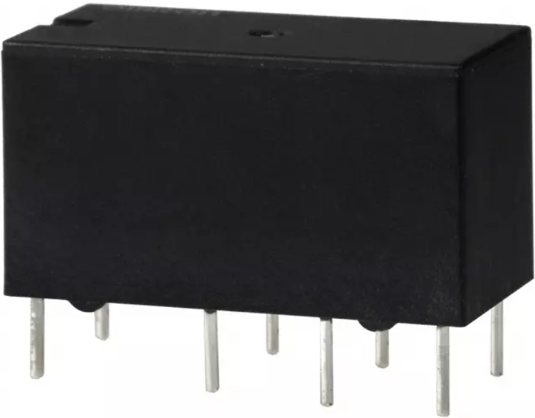
But, how can you find out if your relay has these specs? You check the datasheet!
The Omron G5V-2-H1 DC9, for example, has the Digikey part number Z3673-ND. You can see the relay’s specifications on the Product Attributes table. The Coil Type is specified as Non Latching, which is what we want.
To check the coil polarity we should check the relay’s datasheet
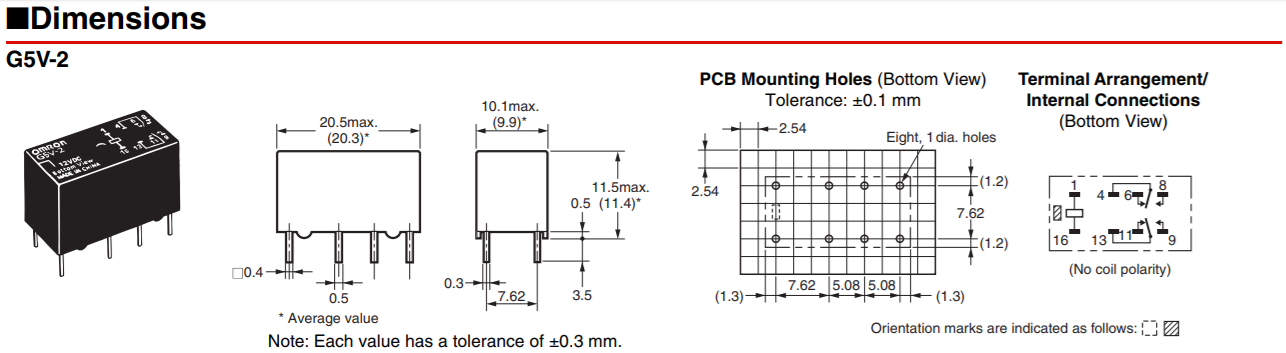
Page 4 shows the dimensions and terminal arrangement of the relay.
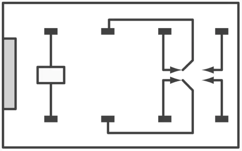
The pin spacing and internal connections of the relay match those from Figure 2-21 of the book.
Below the Bottom View of the Terminal Arrangement/ Internal Connections you see between parentheses that there is no coil polarity
So the Omron G5V-2-H1 DC9 matches all of our requirements!
Test Yourself! Look for the datasheets of the other relay’s recommended by Mr Platt and confirm they match the specifications required.
* Procedure
Don’t confuse the faint click of the relay with the click of the pushbutton.
 Touch the relay’s body if needed, so you can “feel the click” when you press the pushbutton and the contacts in the relay open and close.

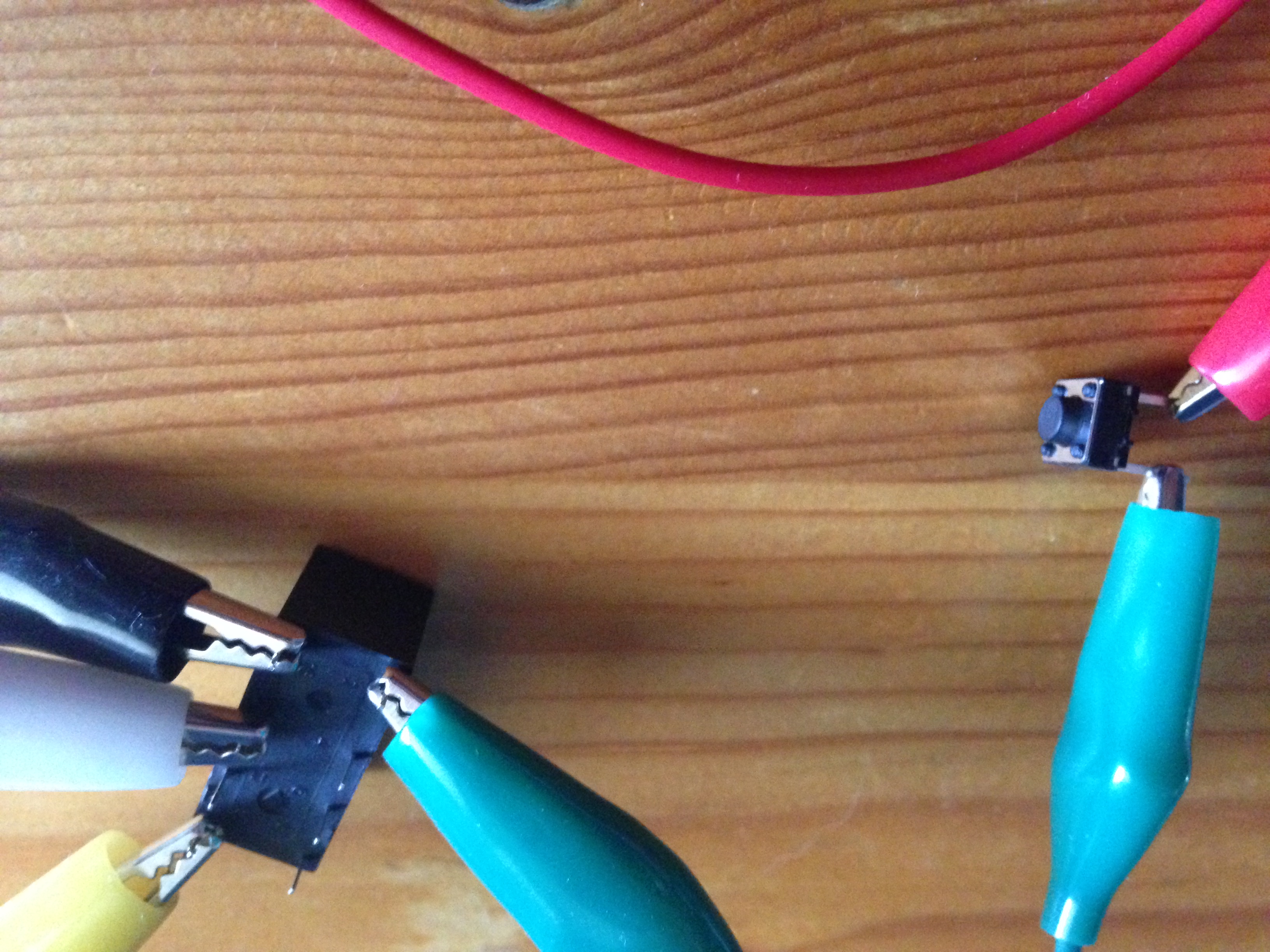
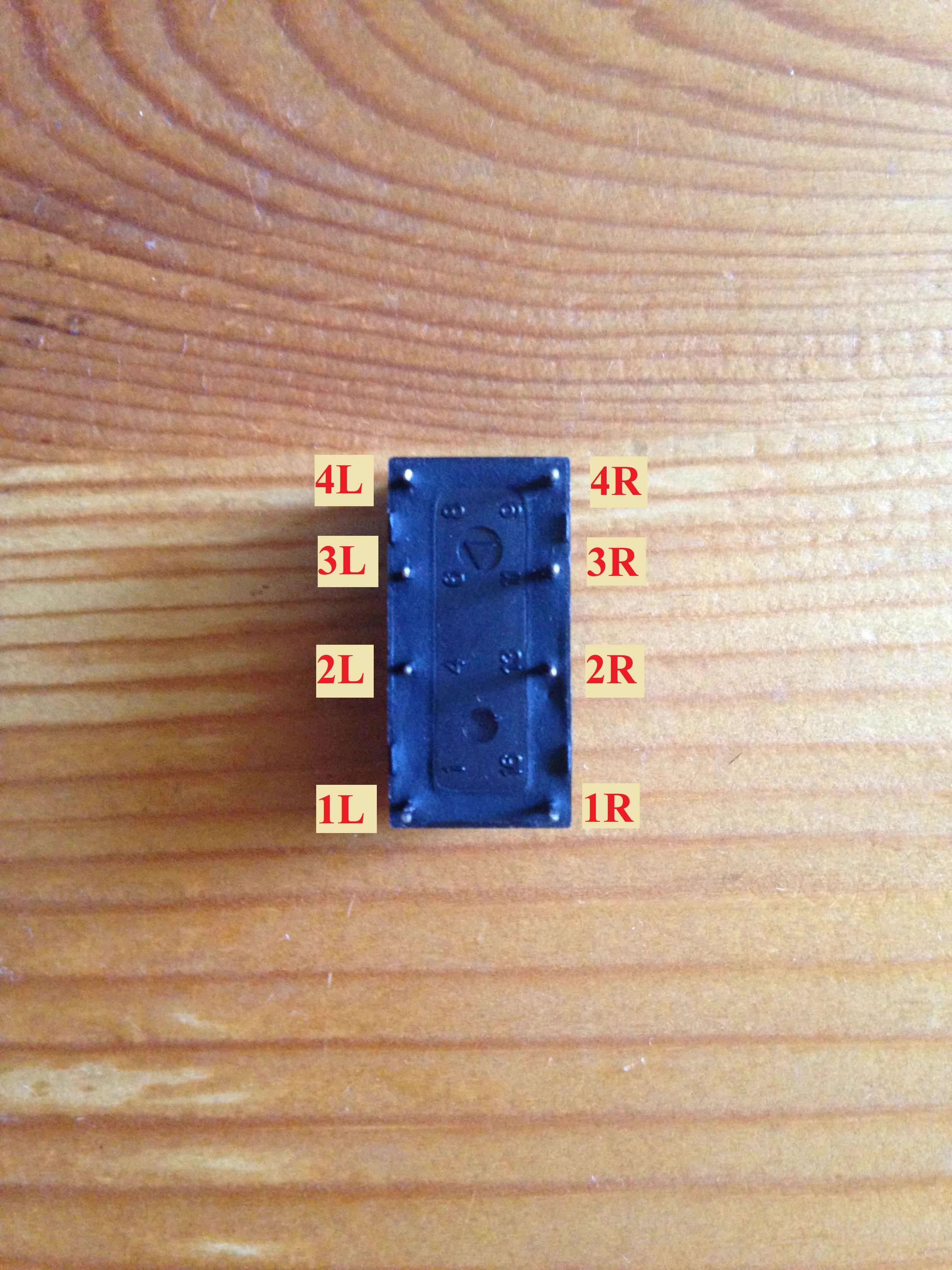
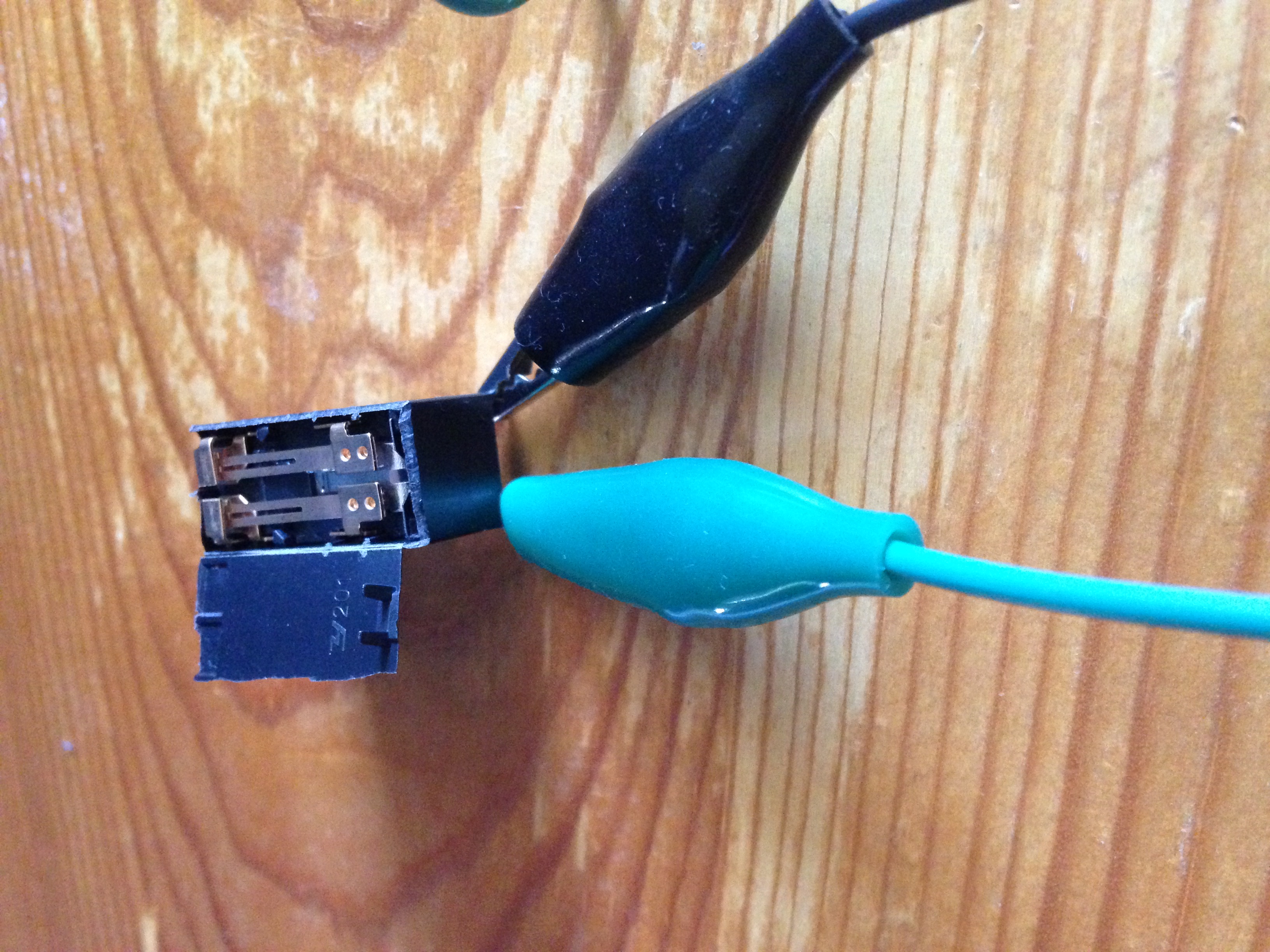
Testing the continuity between two contacts
I’m ready for my close-up
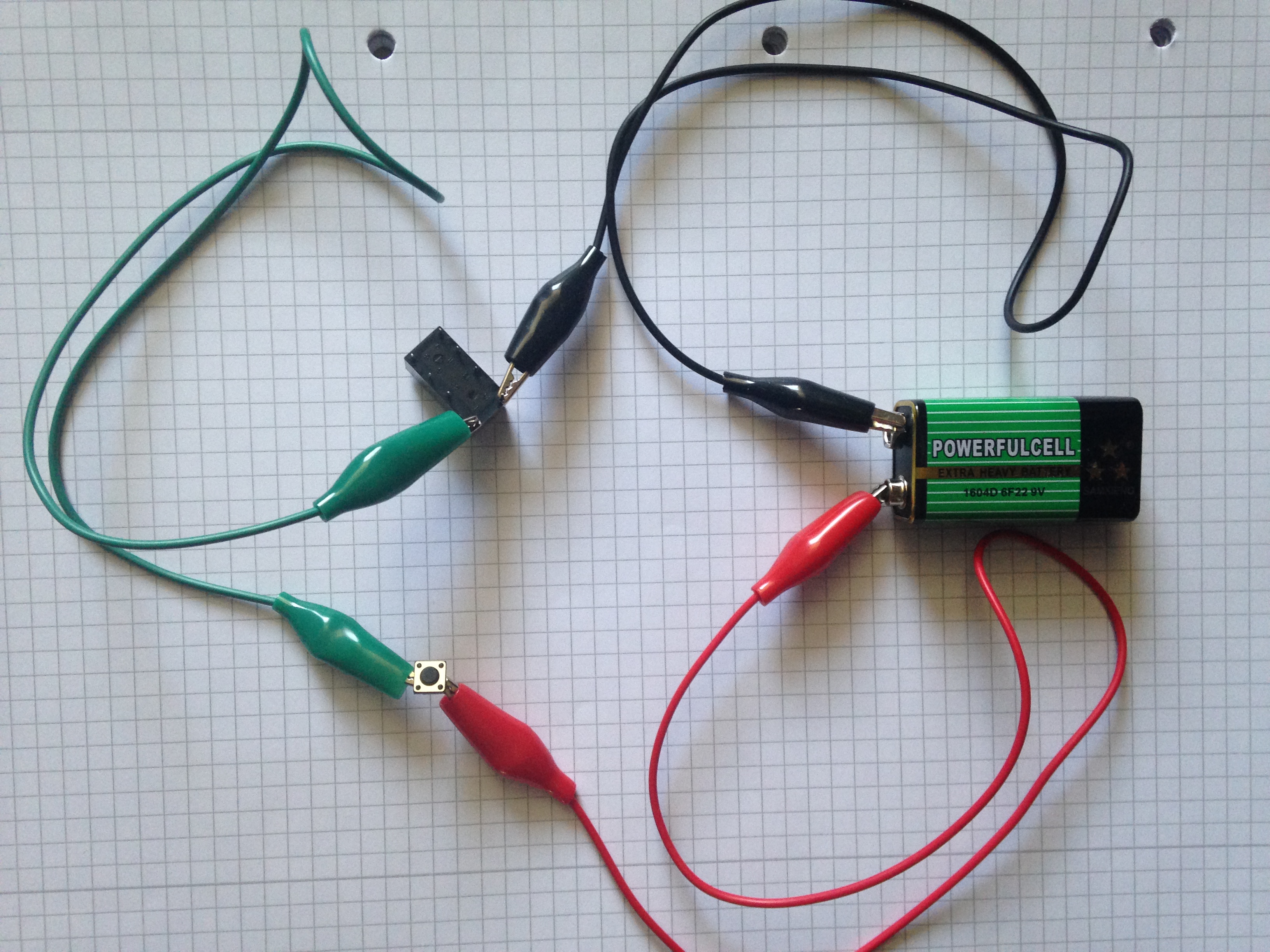
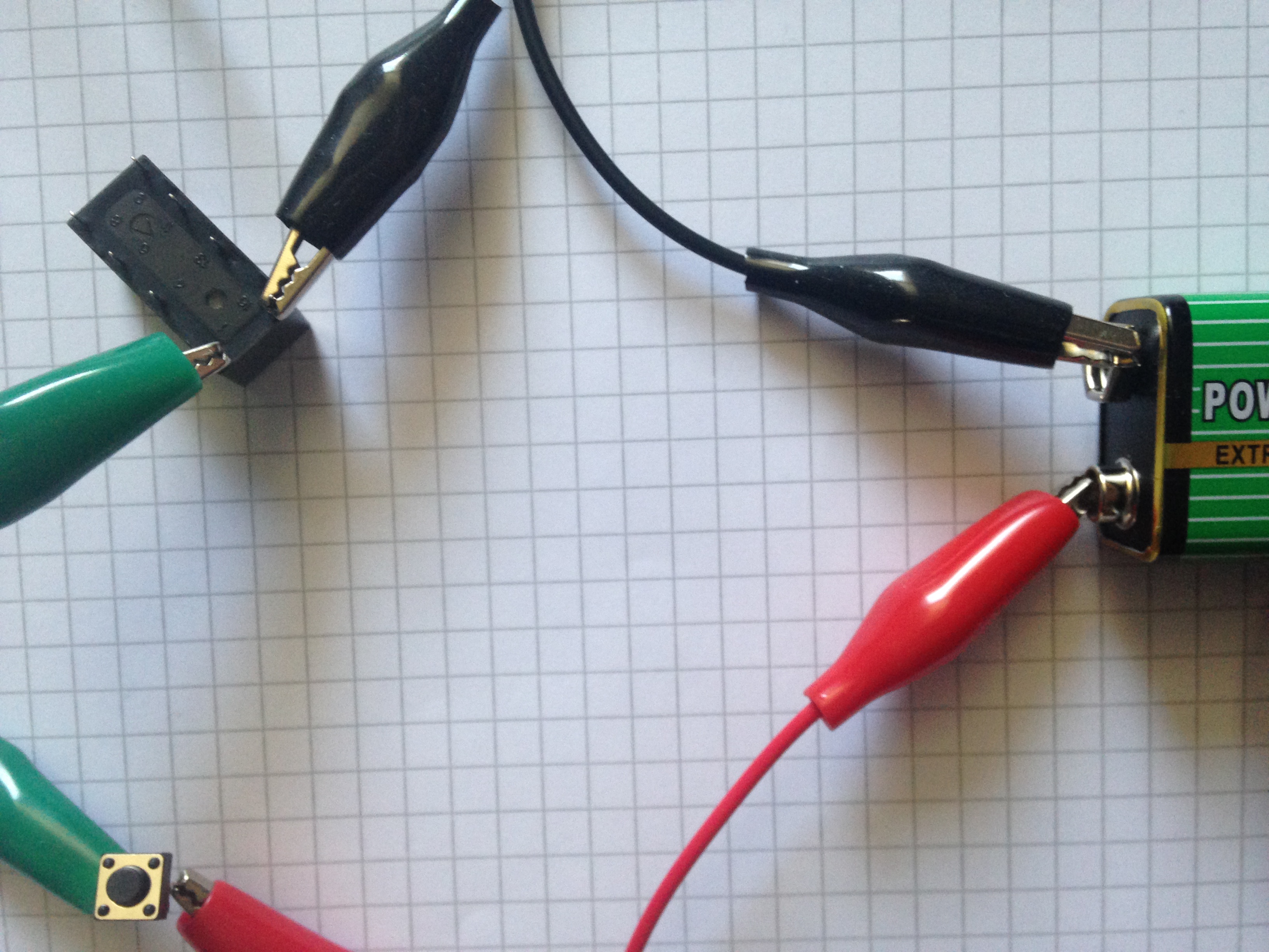
It was tricky to hold the multimeter’s probes against the relay’s contacts while trying to press the pushbutton, which is why I used test leads as shown in Figure 2-51 of the book.
Test the continuity between several contacts both when pressing and not pressing the pushbutton.
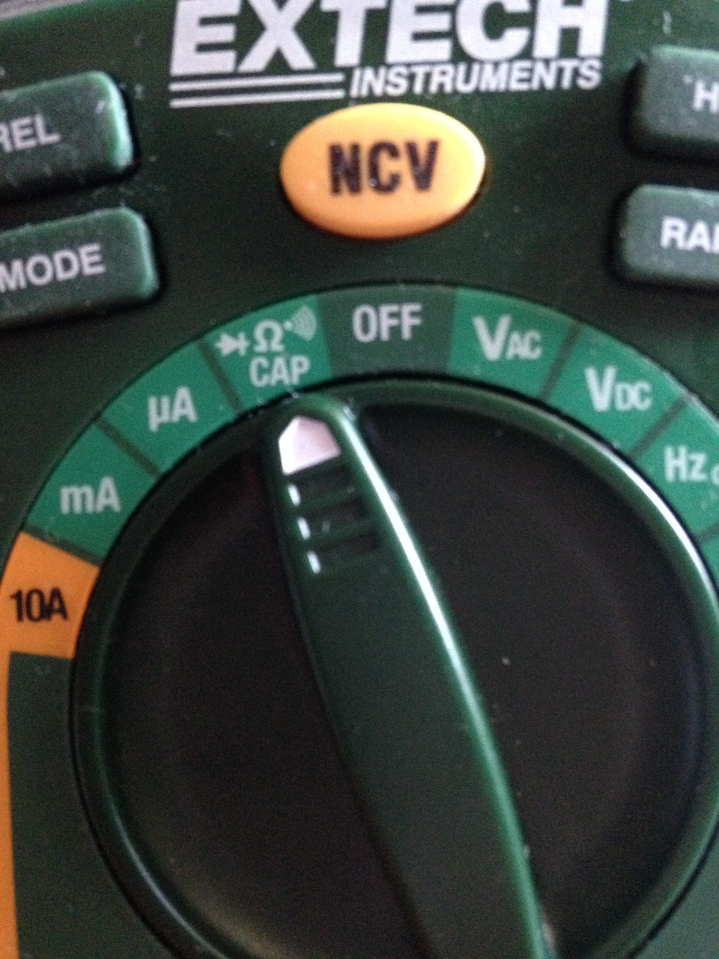
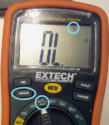
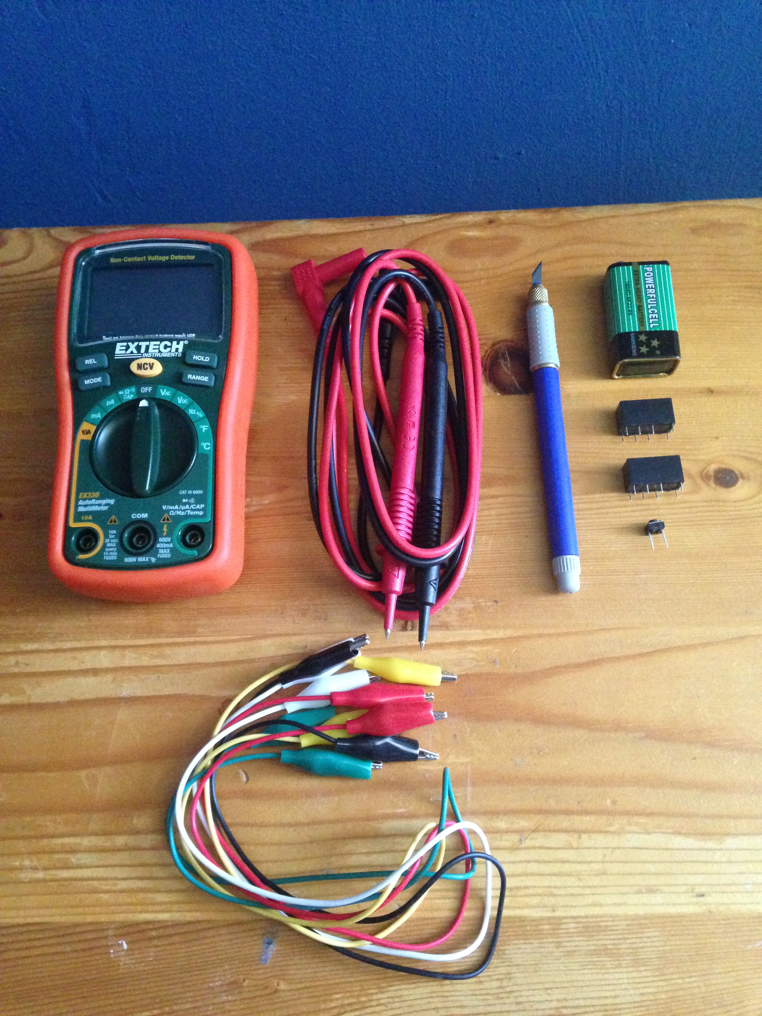
If you don’t know how to measure conductivity with your multimeter be sure to check its manual. If your multimeter is the EXTECH’s EX330, set you meter’s dial to measure continuity and then click the MODE button several times until you see the continuity symbol on the multimeter’s screen.
Testing for Conductivity:
Here are my results!
|
Pushbutton pressed |
|
| 2R and 3R |
No conductivity |
| 2R and 4R |
Conductivity |
| 3R and 4R |
No conductivity |
|
Pushbutton not pressed |
|
|
2L and 3L |
Conductivity |
| 2L and 4L |
No conductivity |
| 3L and 4L |
No conductivity |
But what about testing the conductivity between the contacts on the left and right sides of the relay?
Feel free to try, but there’s no conductivity whatsoever between the left and right sides of the relay.
To understand why, read the “What’s Going On Inside” and “Other Relays” sections of the experiment. Can you now better understand how your relay works? There’s no conductivity between the left and right contacts of the relay because they’re two different poles!
* Opening It Up
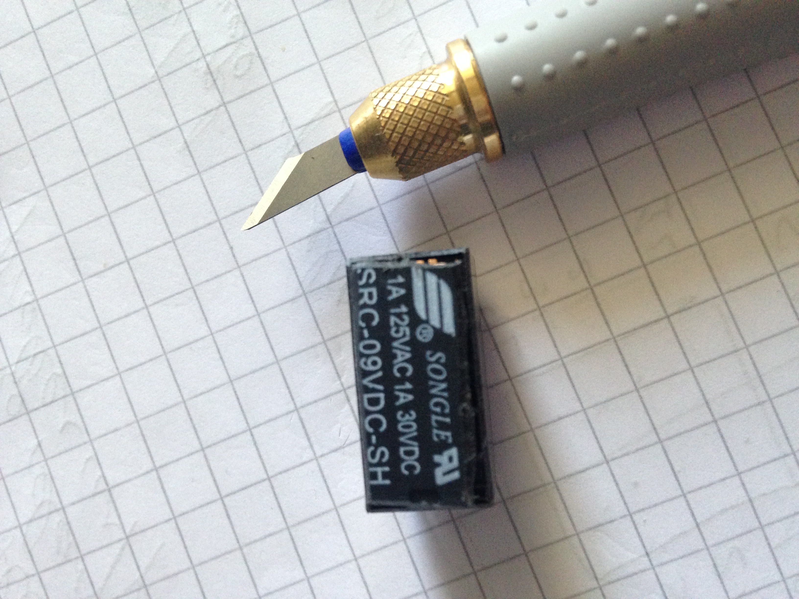
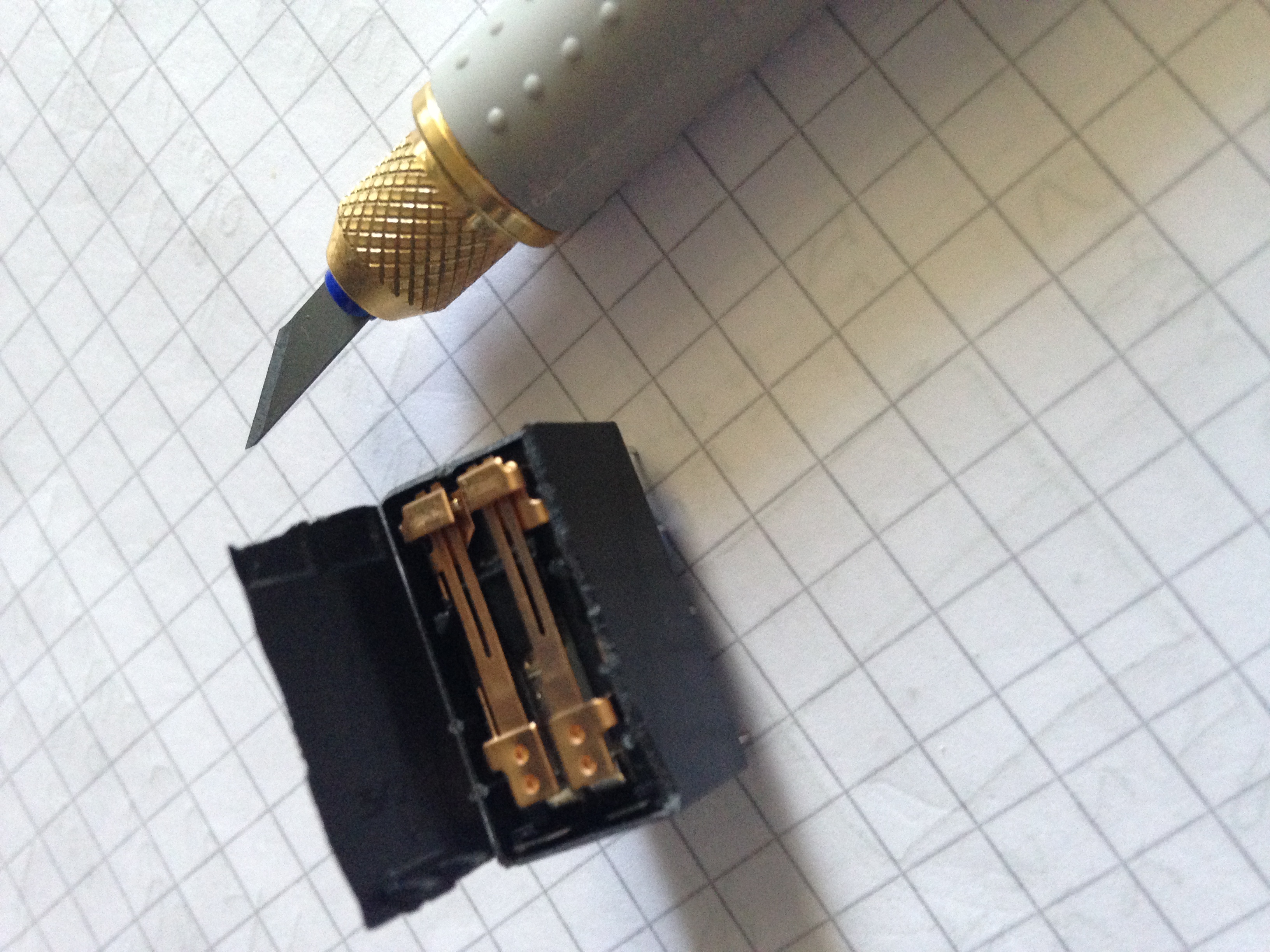
Be sure to always move the knife away from you. Work slowly and be patient.
It’s not a sprint, if you get tired, ask for help and make it a relay! ☺
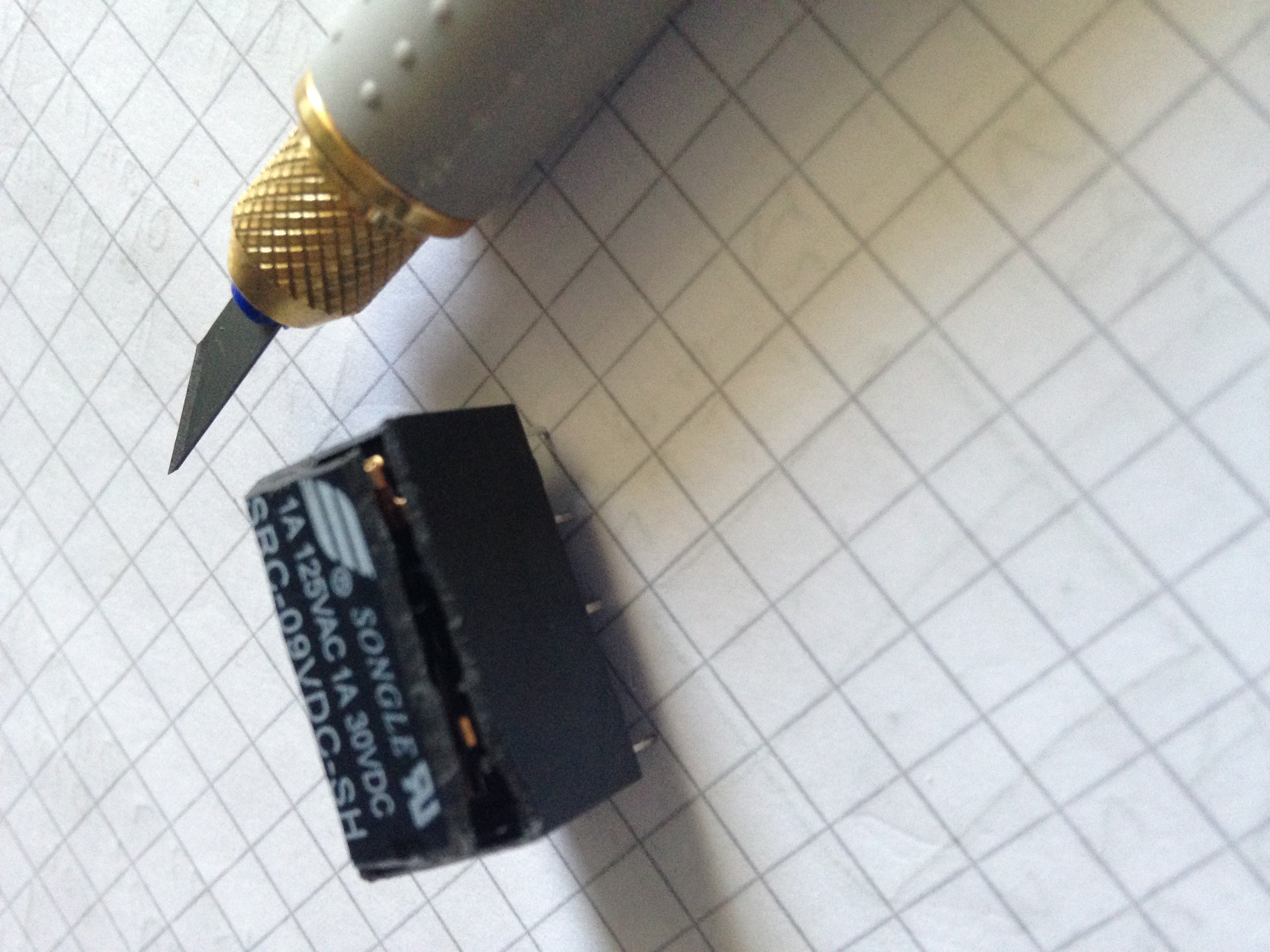
Don’t shave the edges of the plastic shell any more than you have to, so you can continue using this relay in later experiments.
Connect the relay again, this time, when you press the pushbutton and current passes through the coil, you will be able to see the insides of the relay moving.
Lastly, read the “Fundamentals: Relay Terminology” section of the experiment.
Practice looking for the all the terms introduced in this section of the book for the Omron G5V-2-H1 DC9
Hint: The switching capacity is specified for a resistive load.
Learning how to find components with the right specifications is an essential skill that will help you save time and money as you move forward with your learning.