Experiment 8: A Relay Oscillator

Long, long time ago, in the time before sliced bread, people would use boards of wood to slice bread on. Later, these “bread boards” would be used to build circuits on.


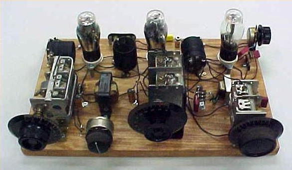
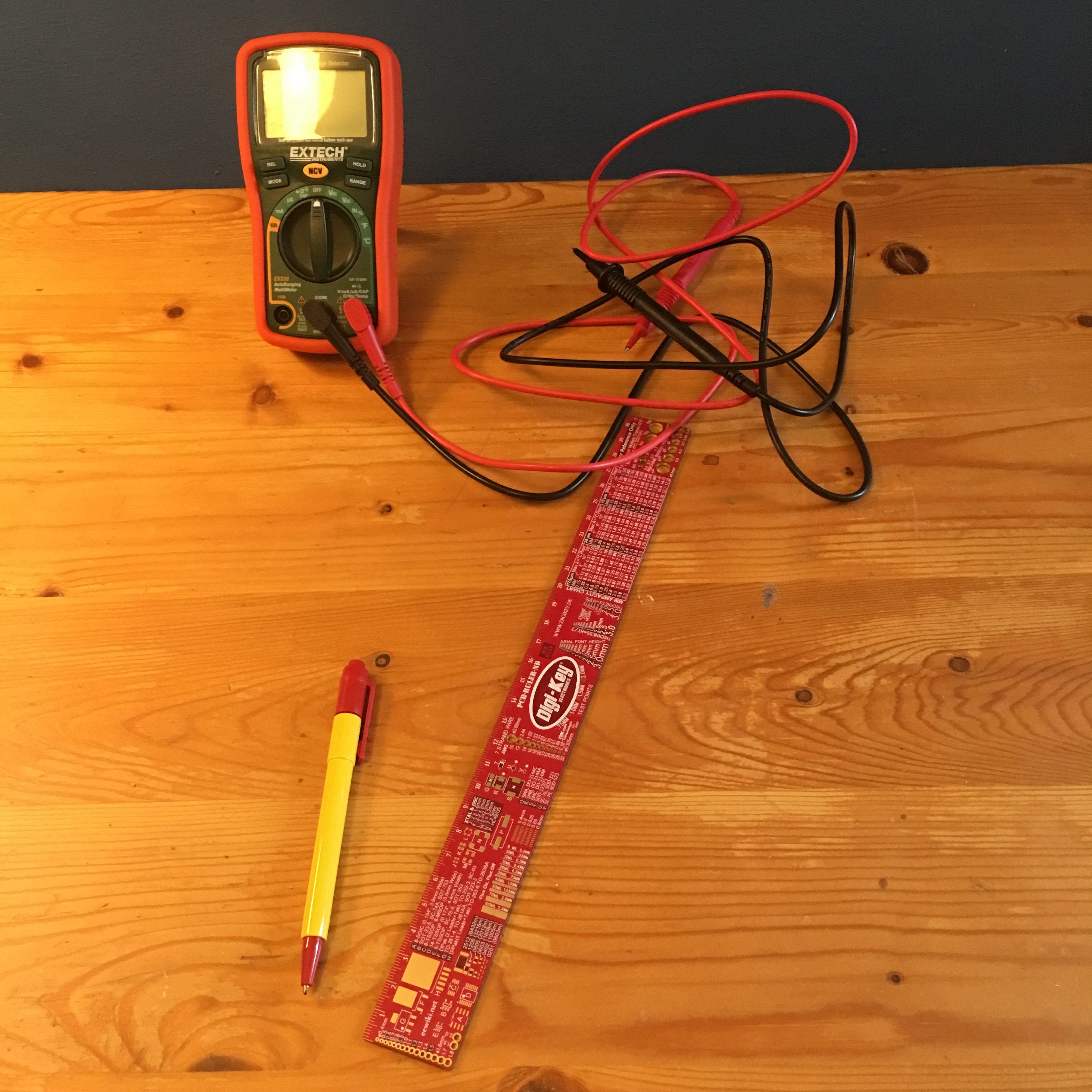
Worry not! nowadays, prototyping boards are widely available.
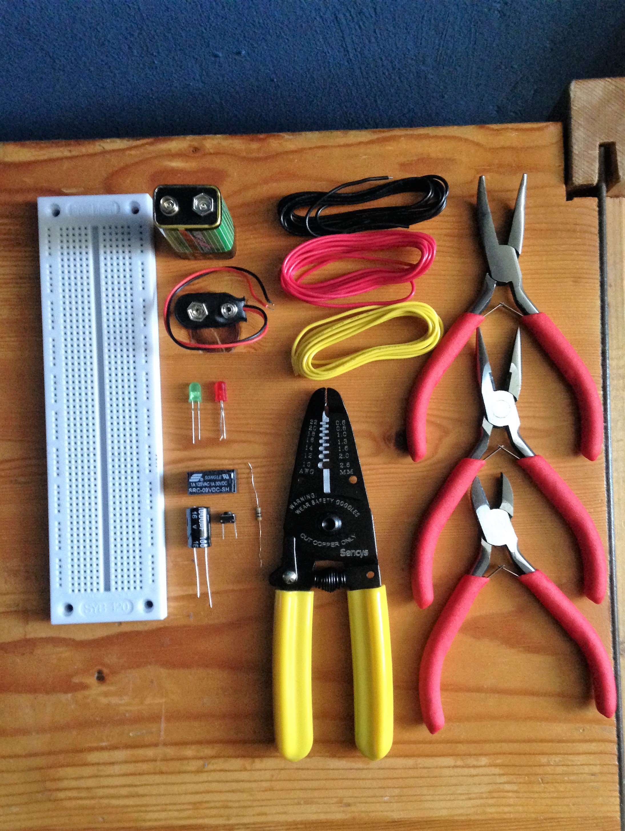
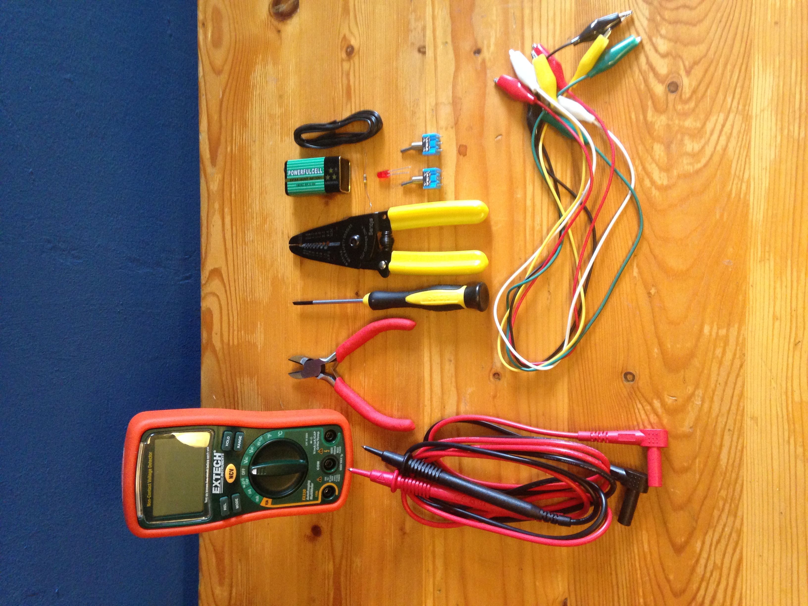
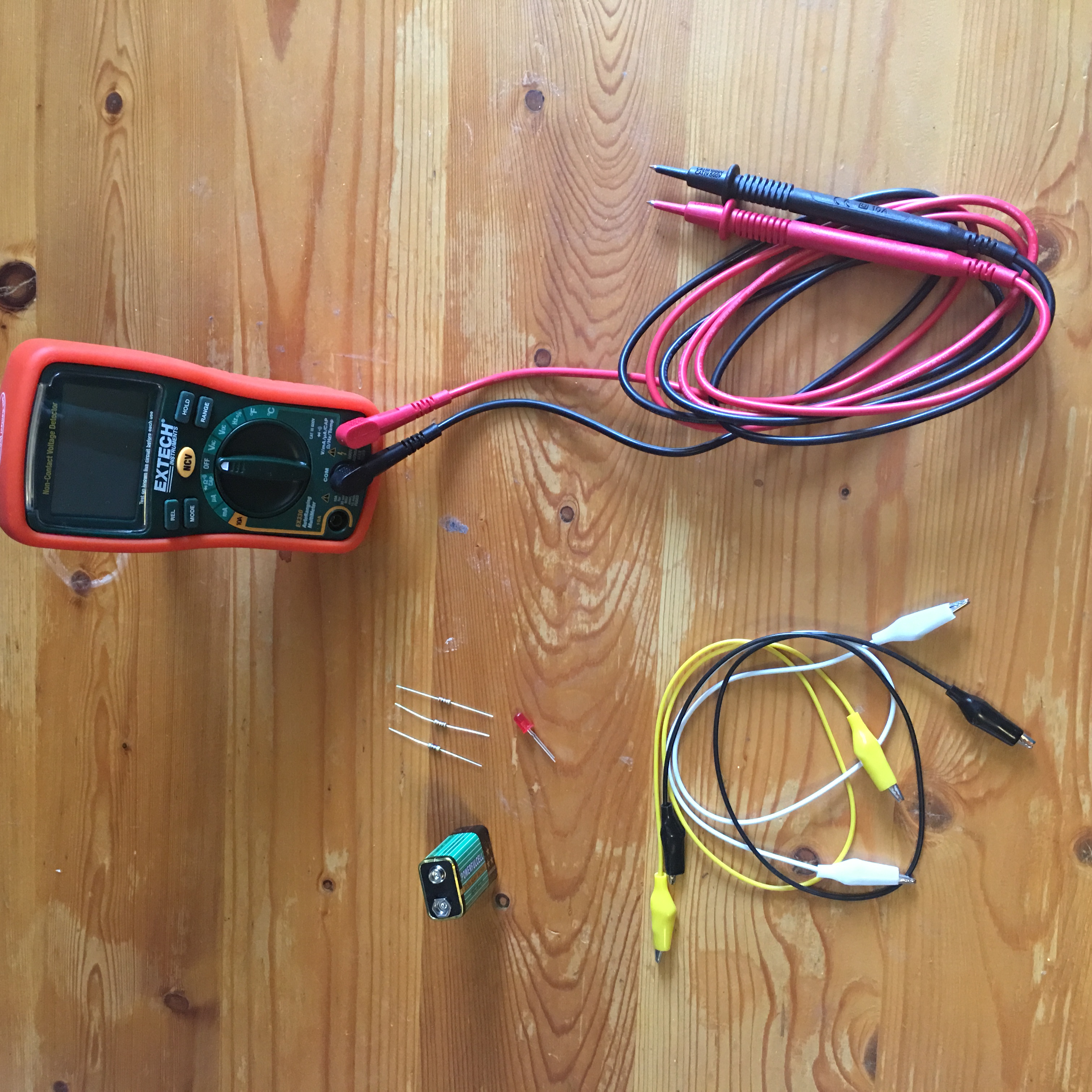
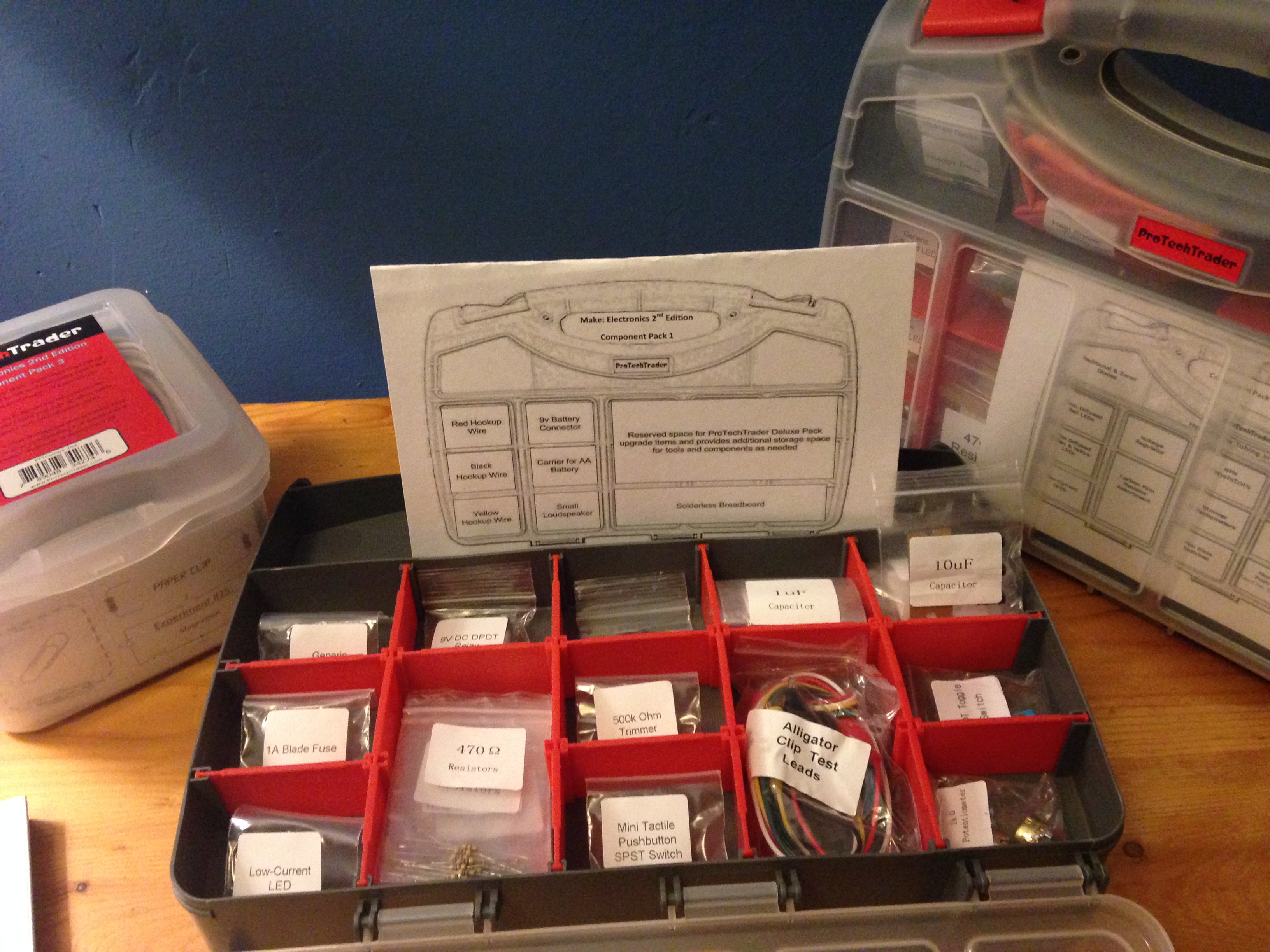
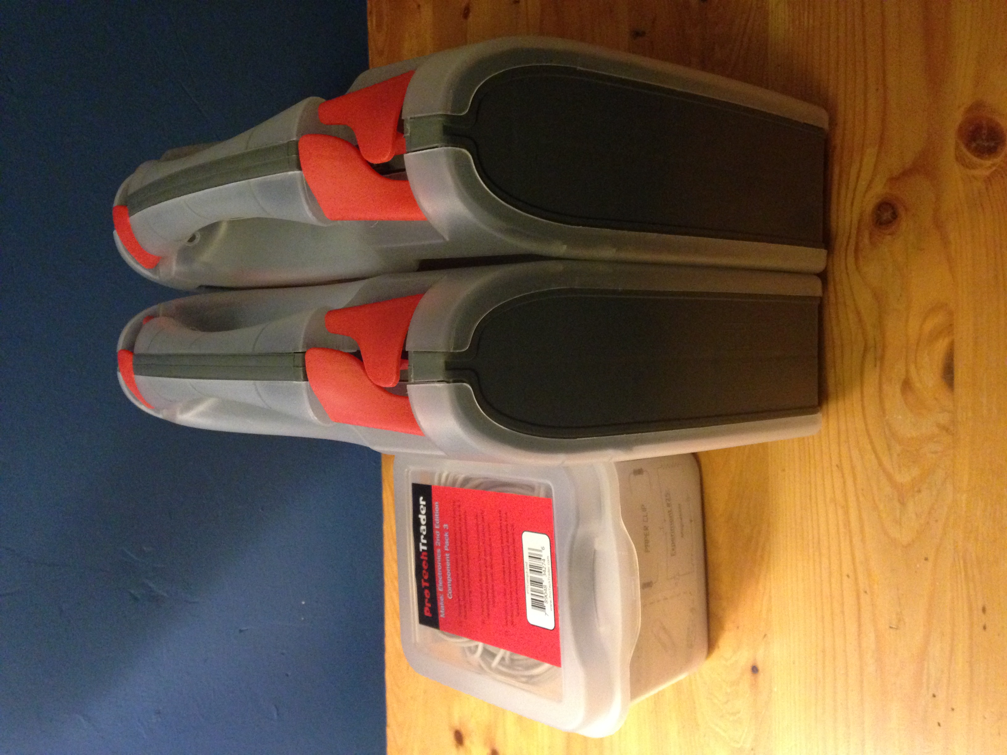
* A Beginner’s Board

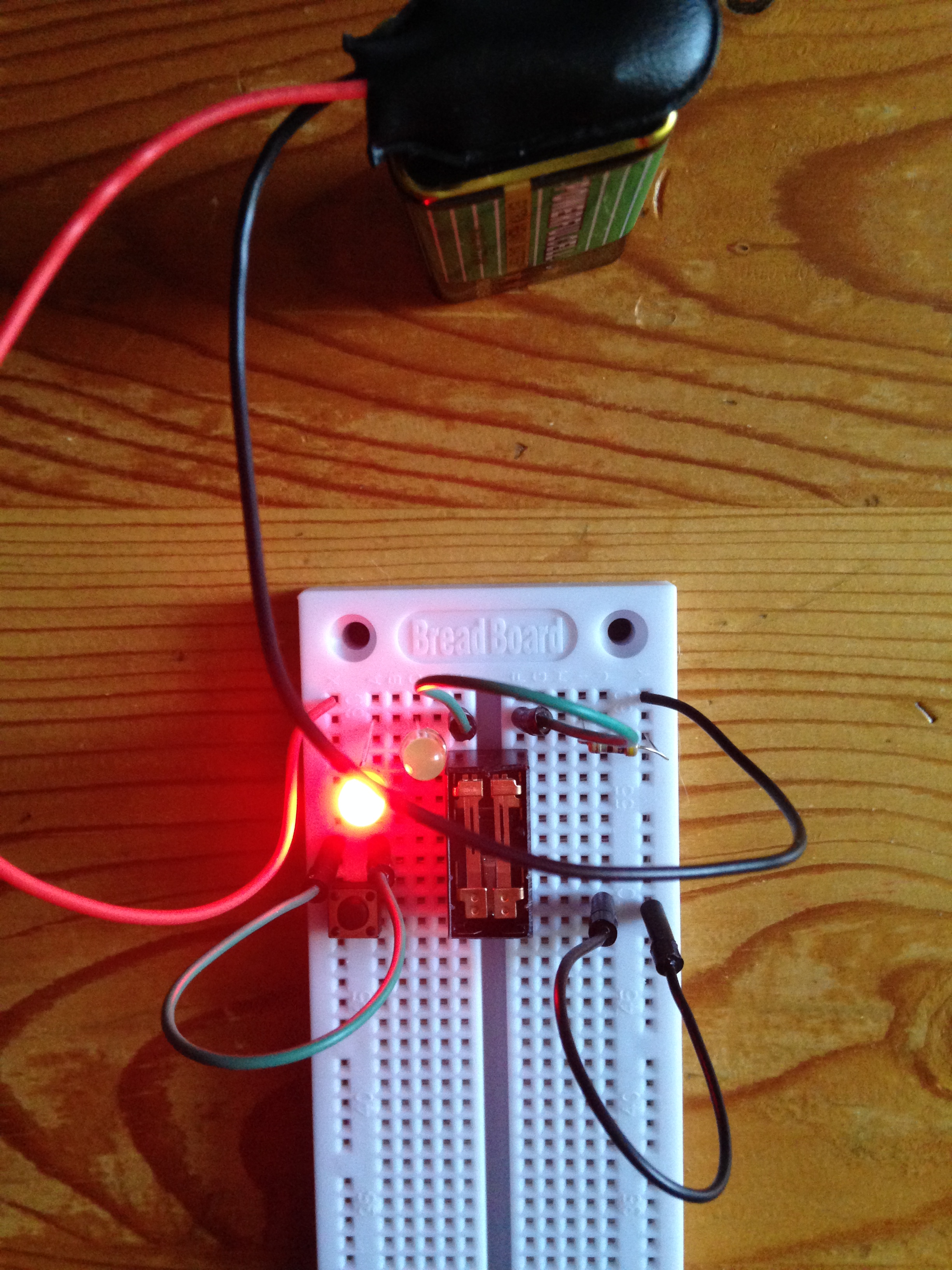
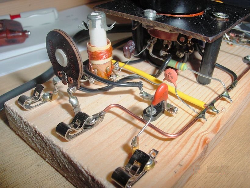
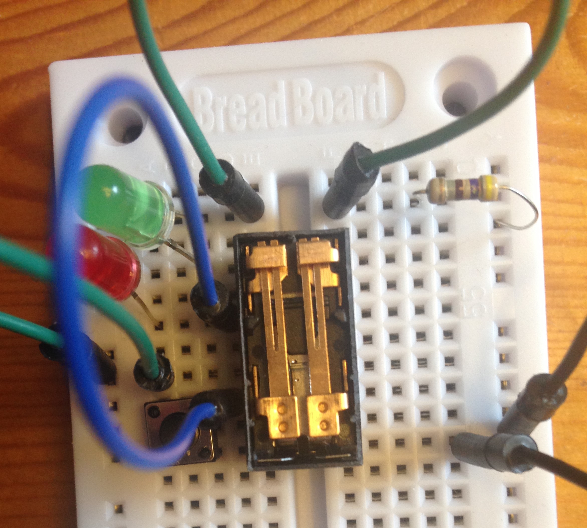
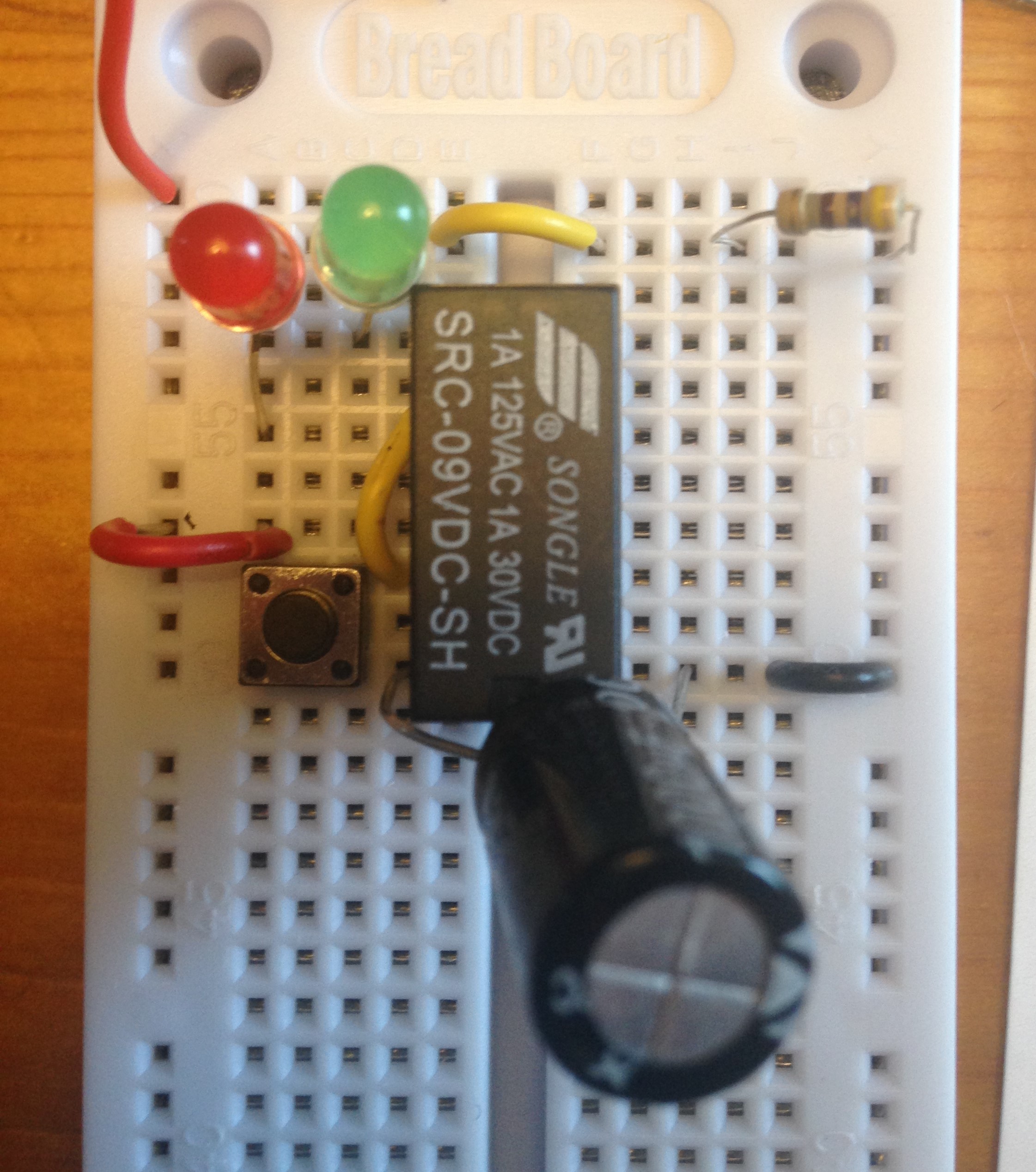
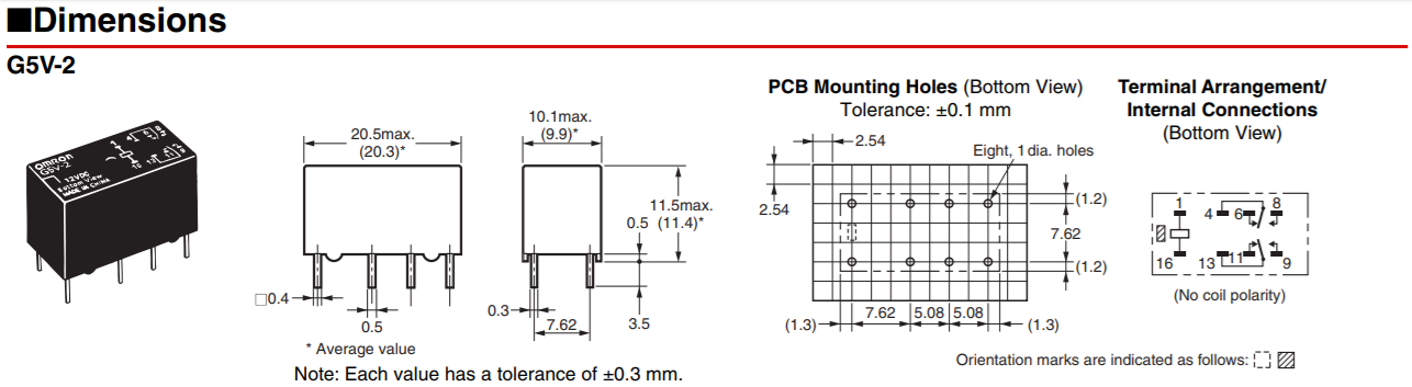
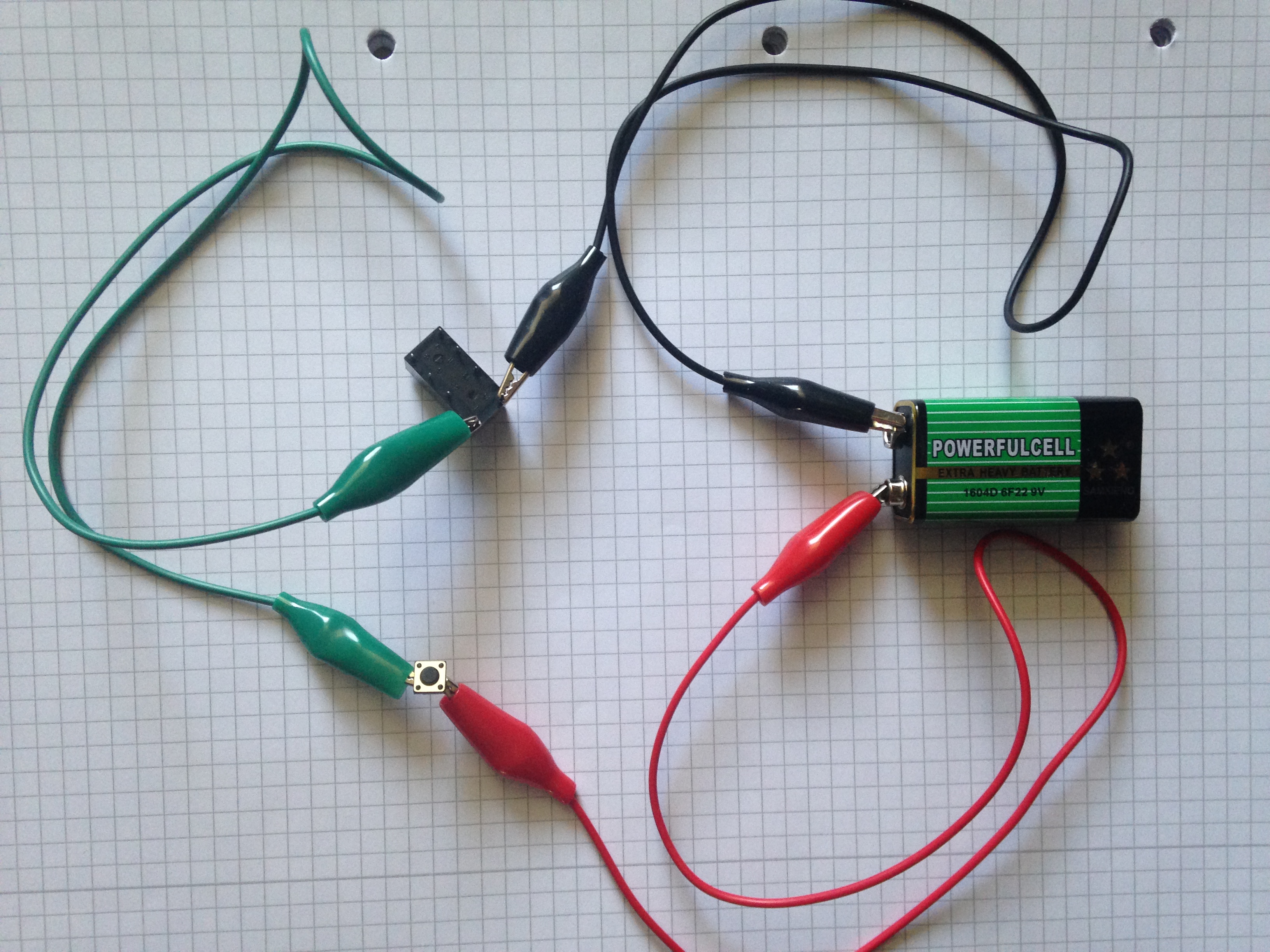
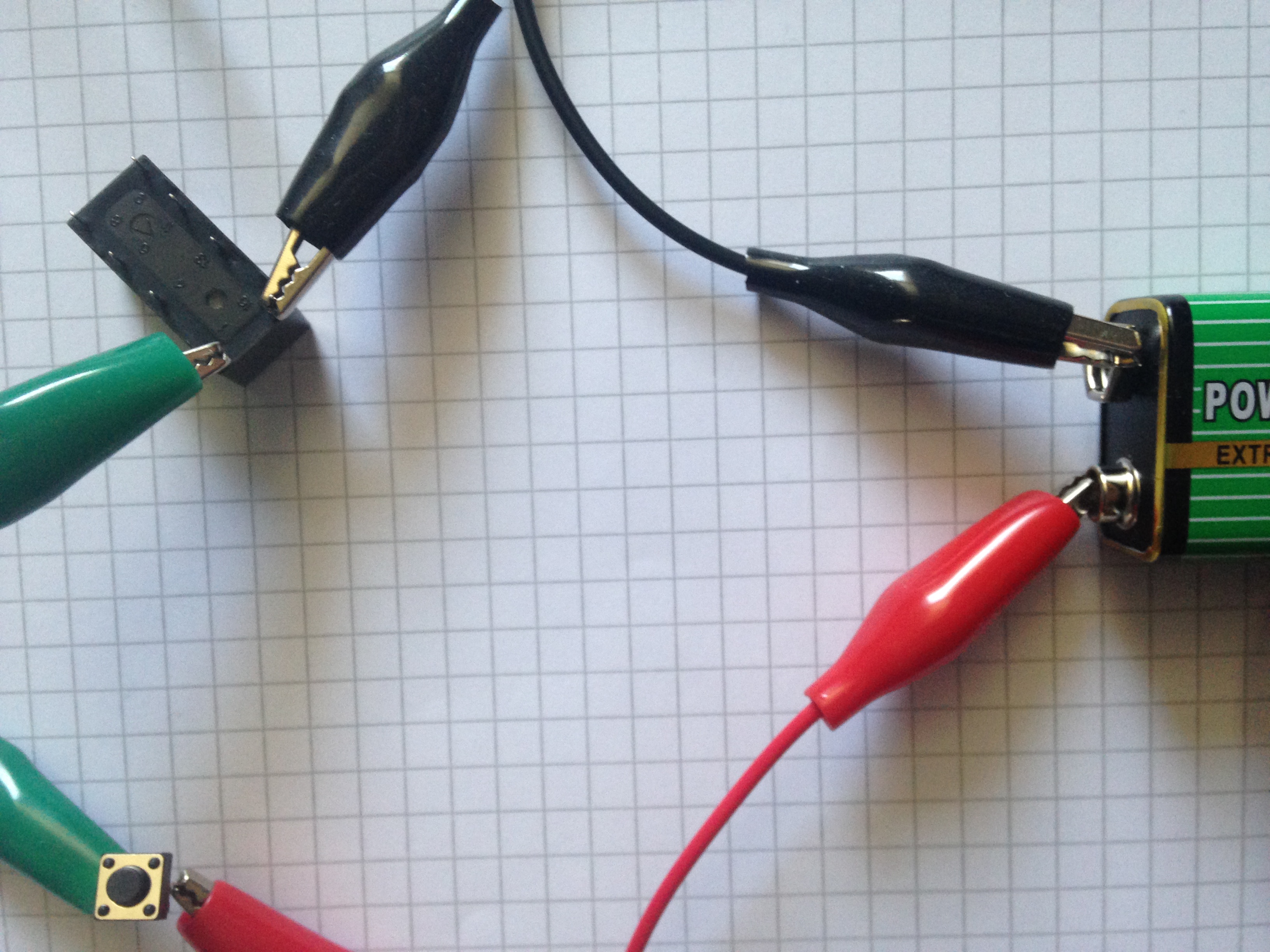
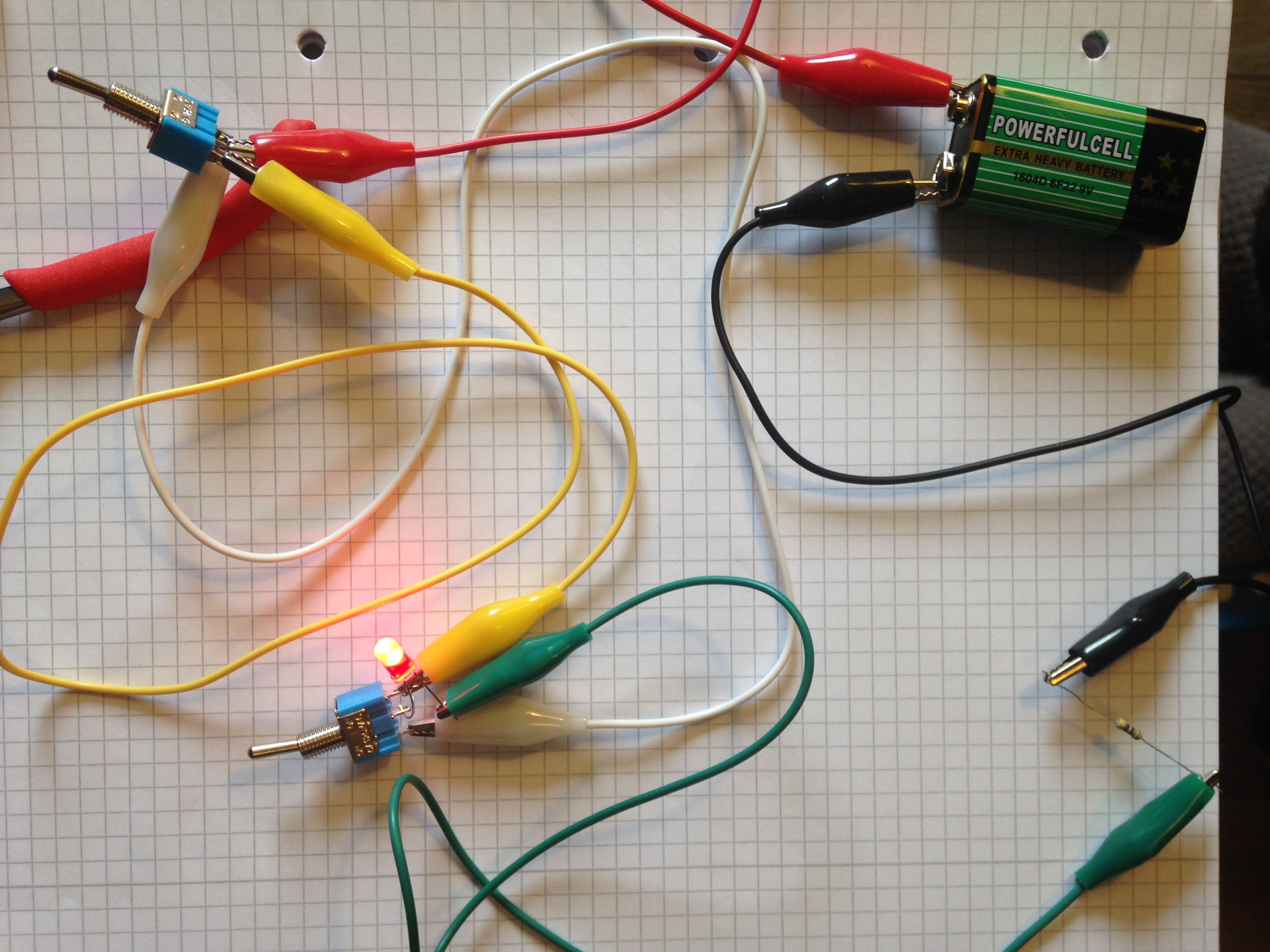
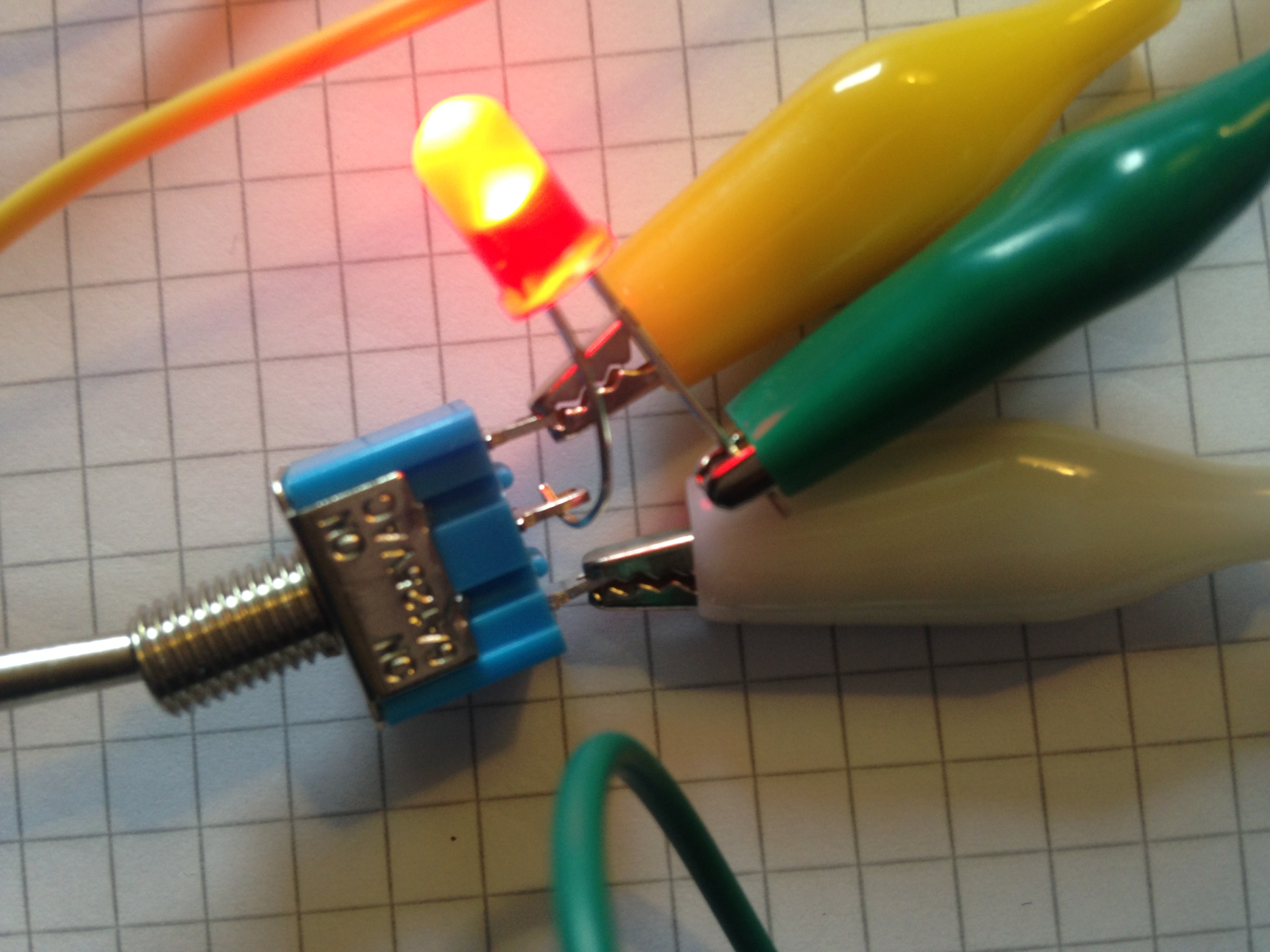
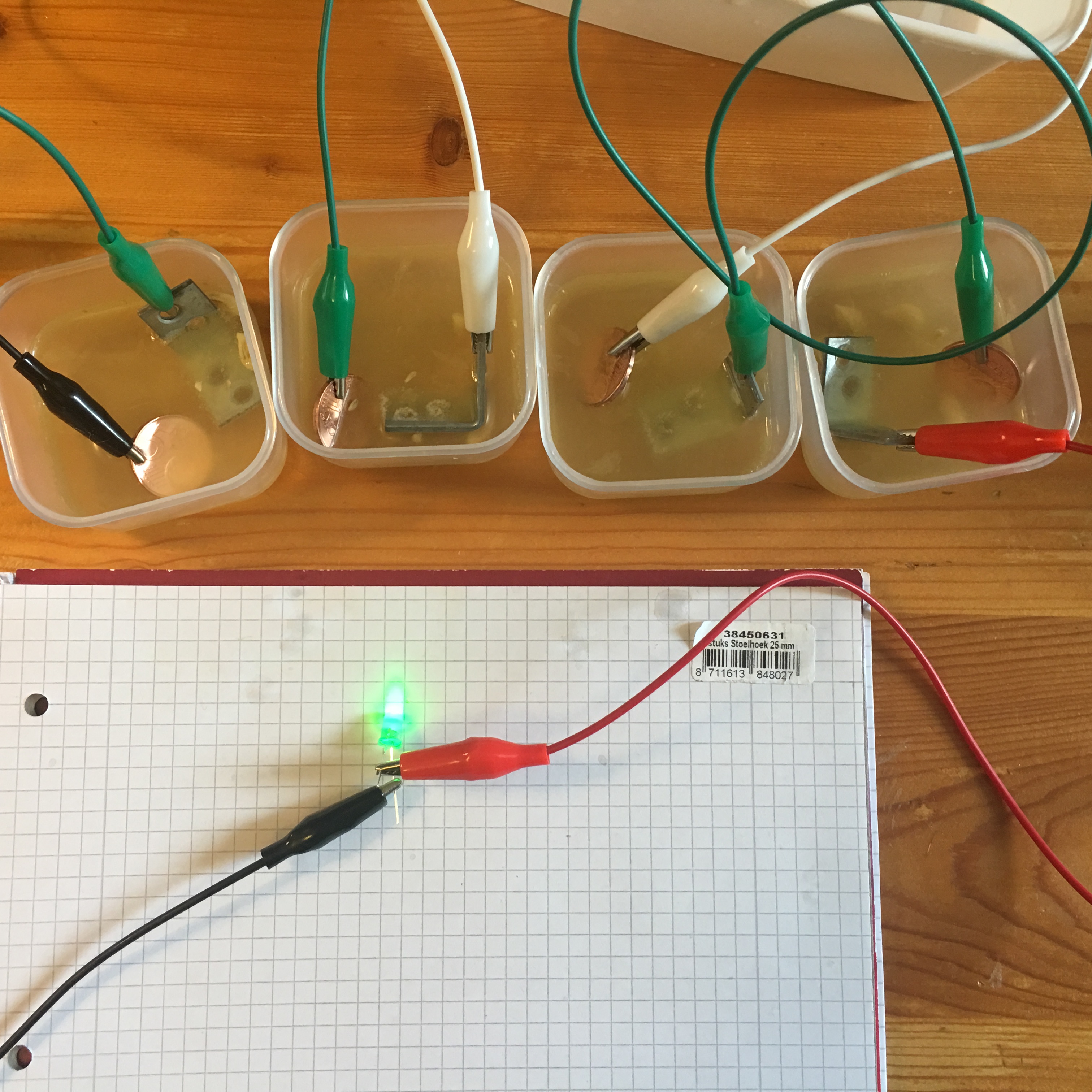
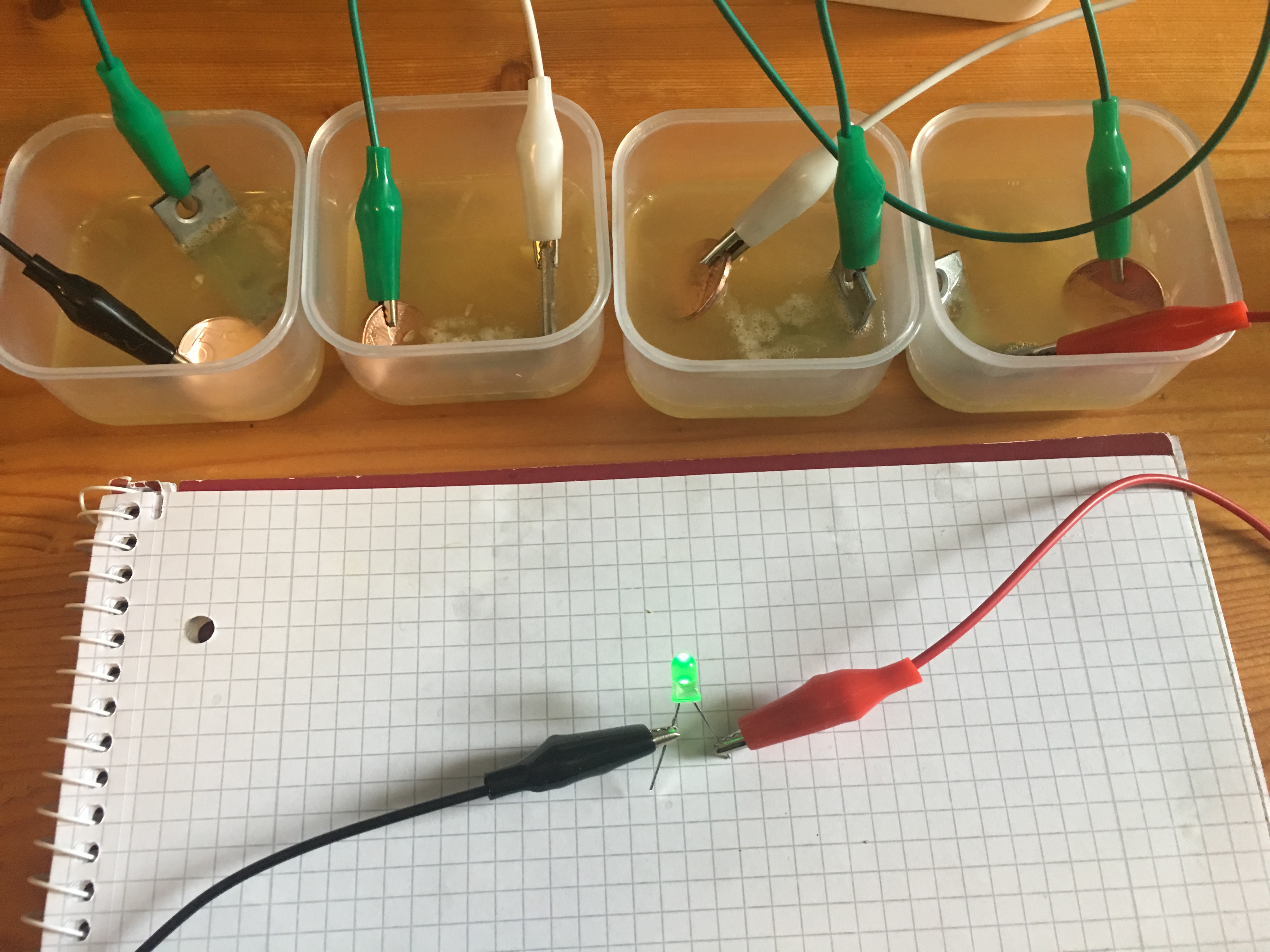
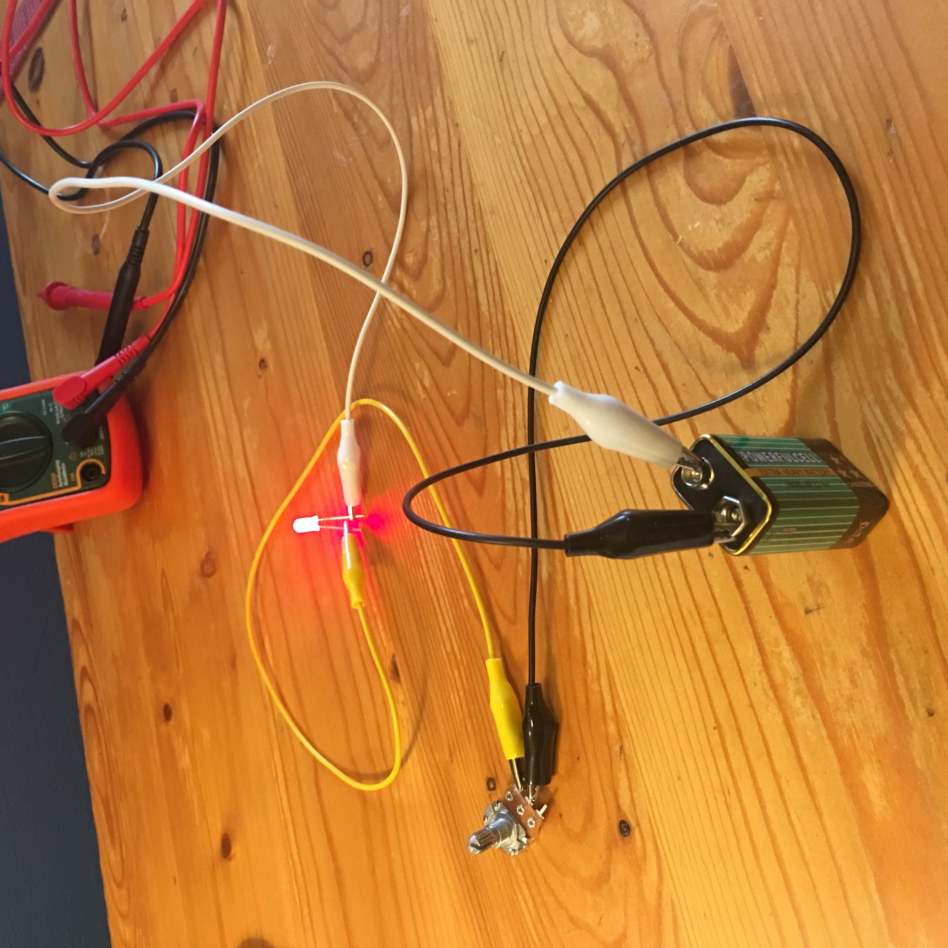
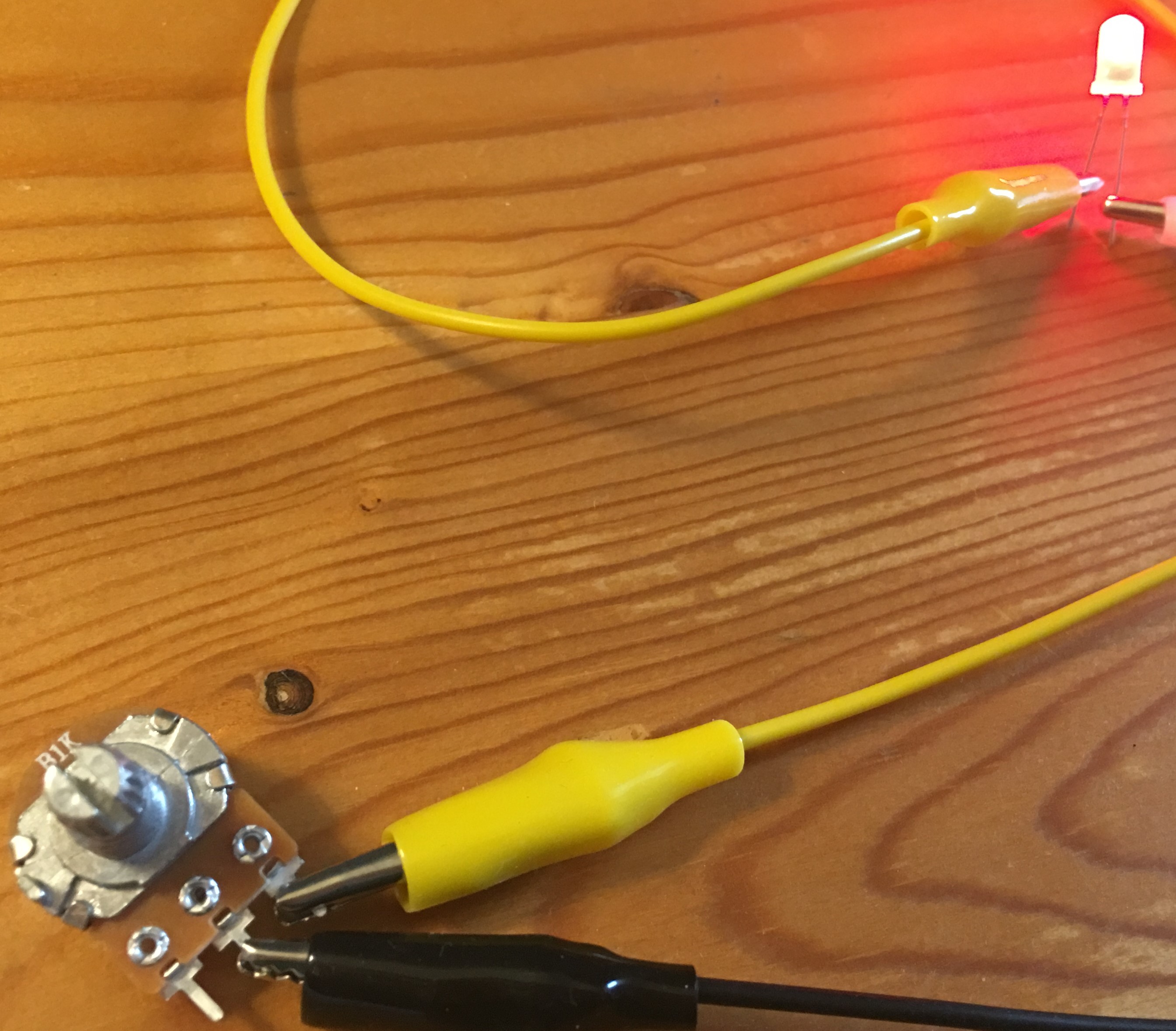
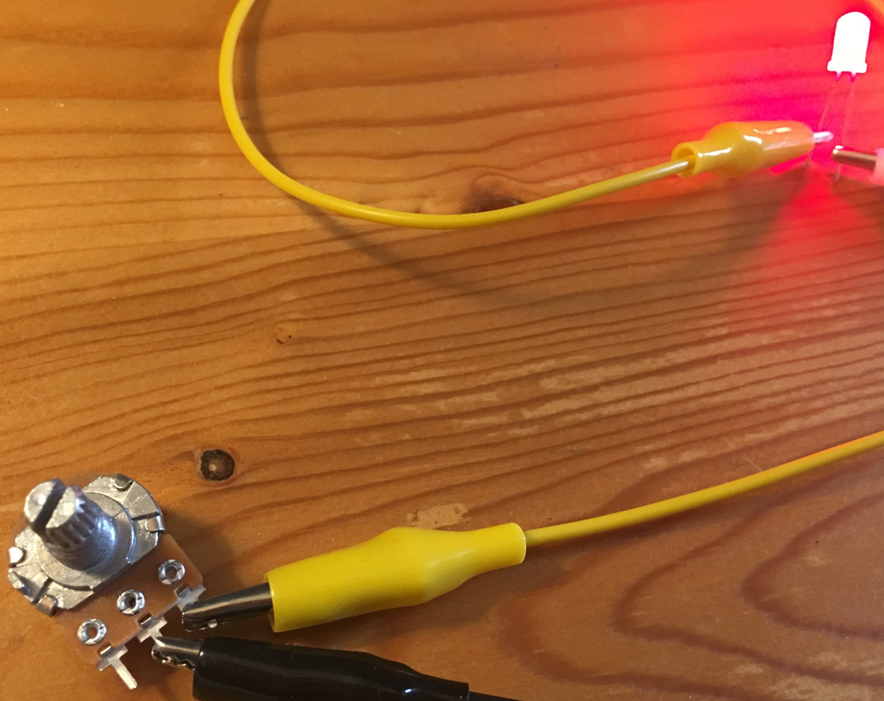
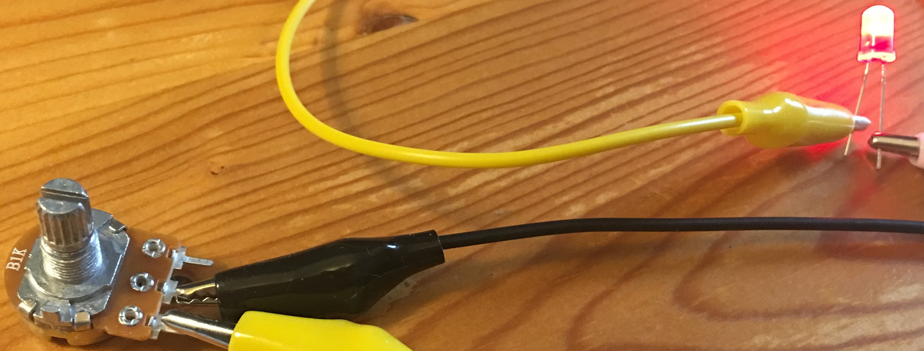
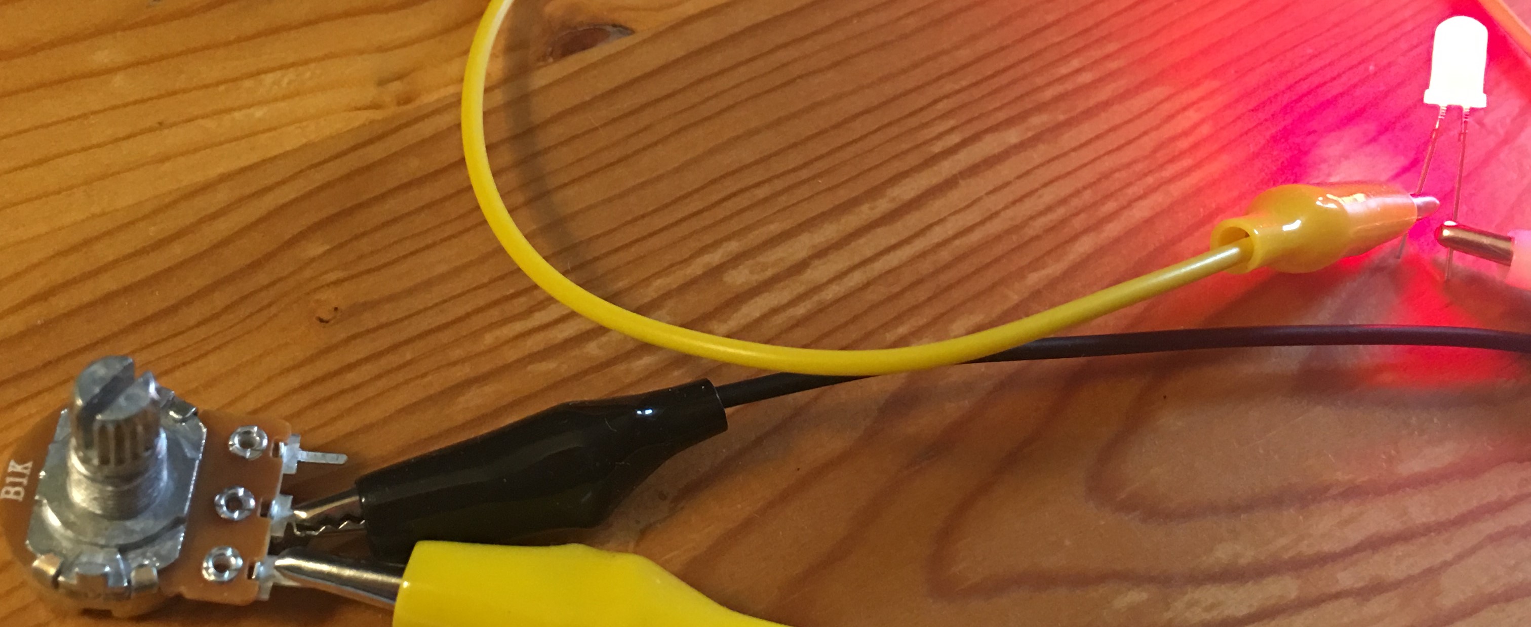
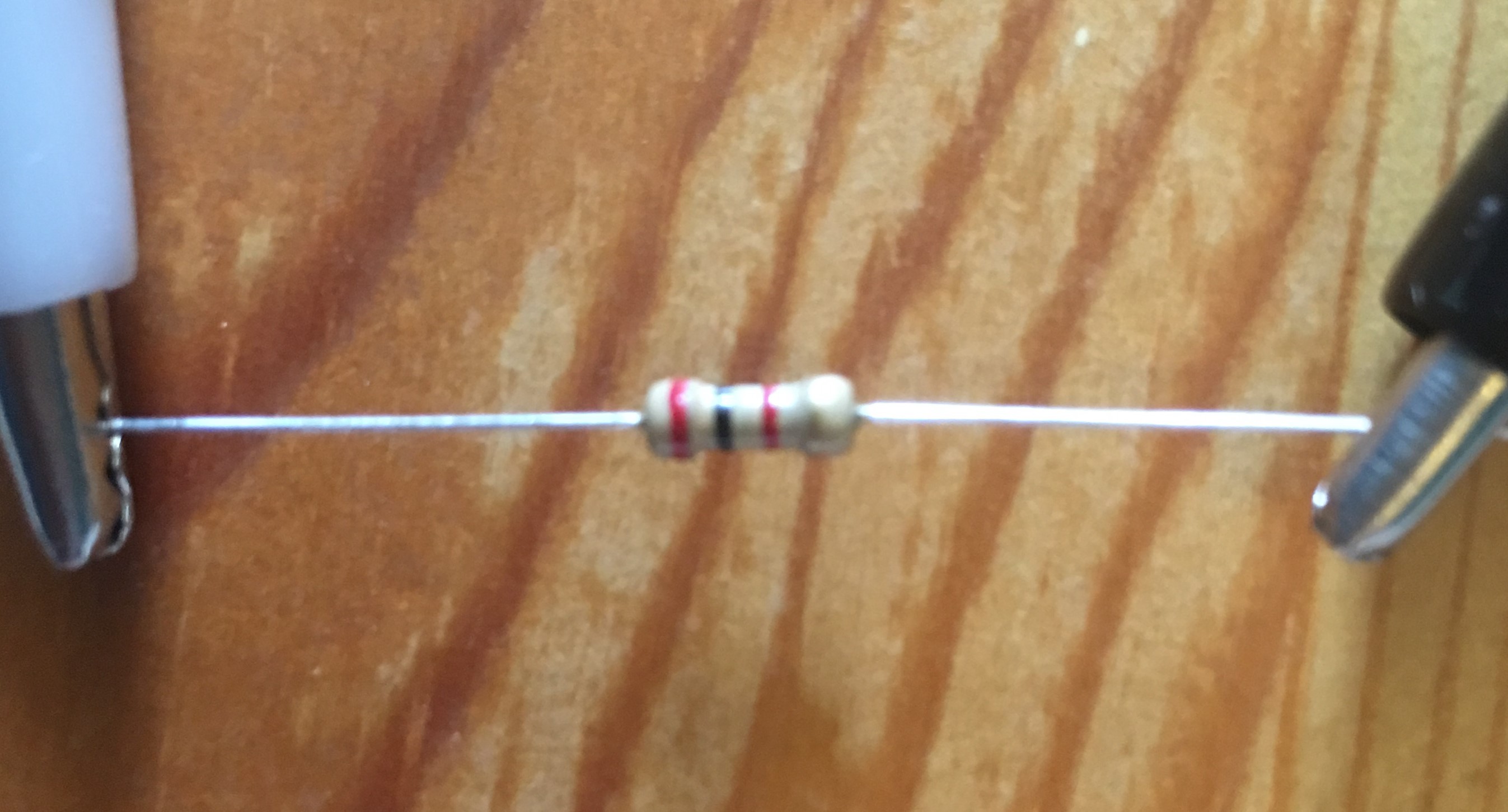
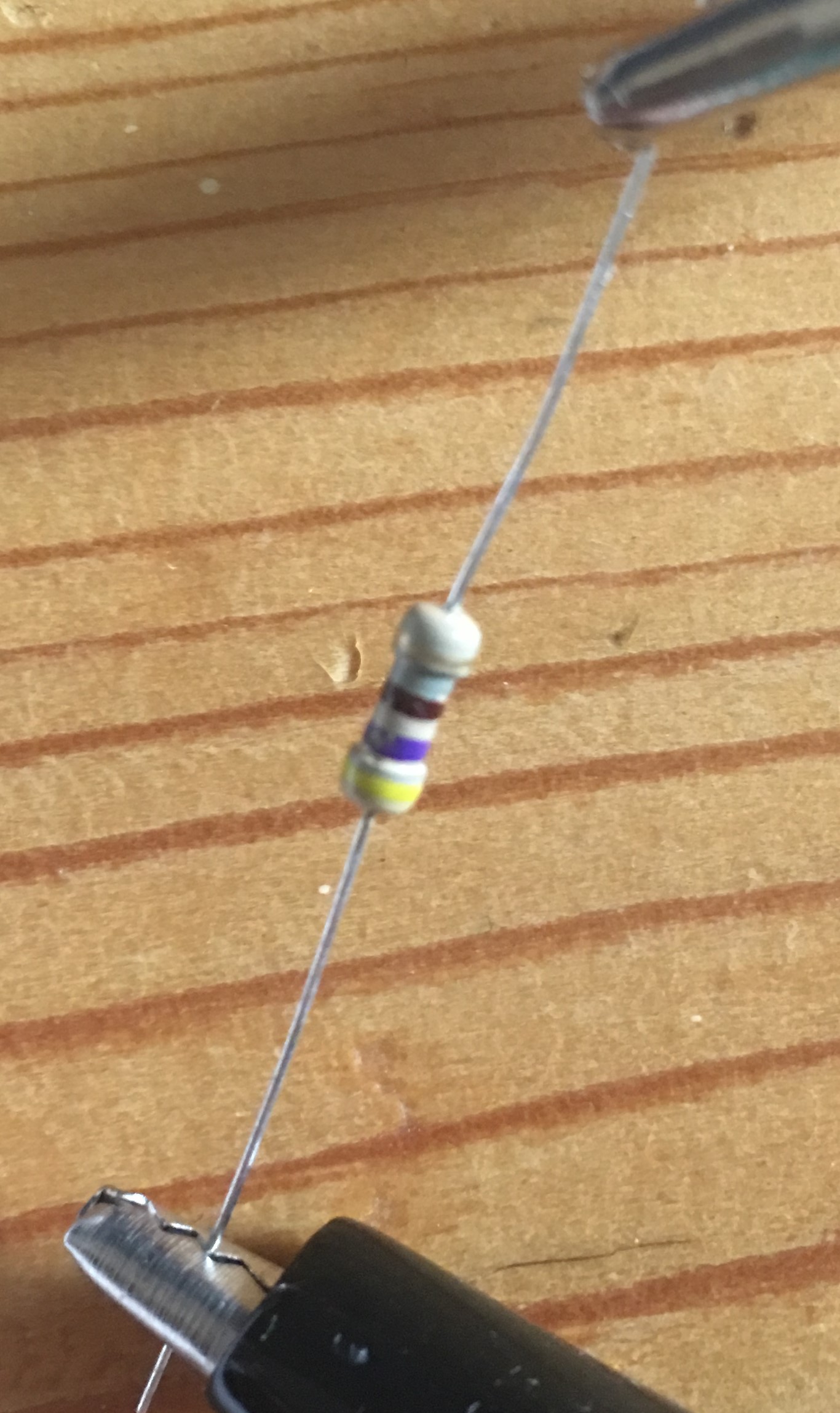
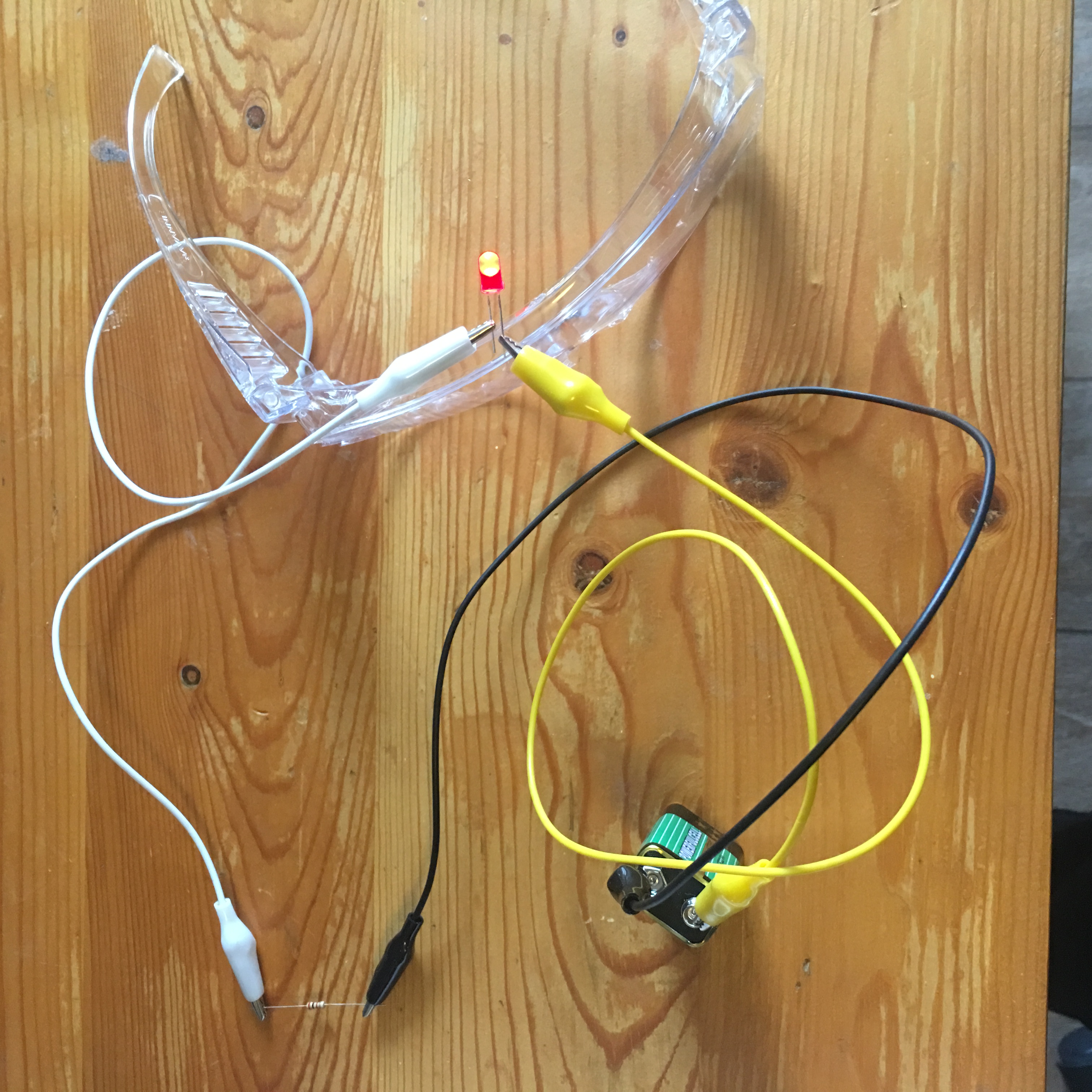
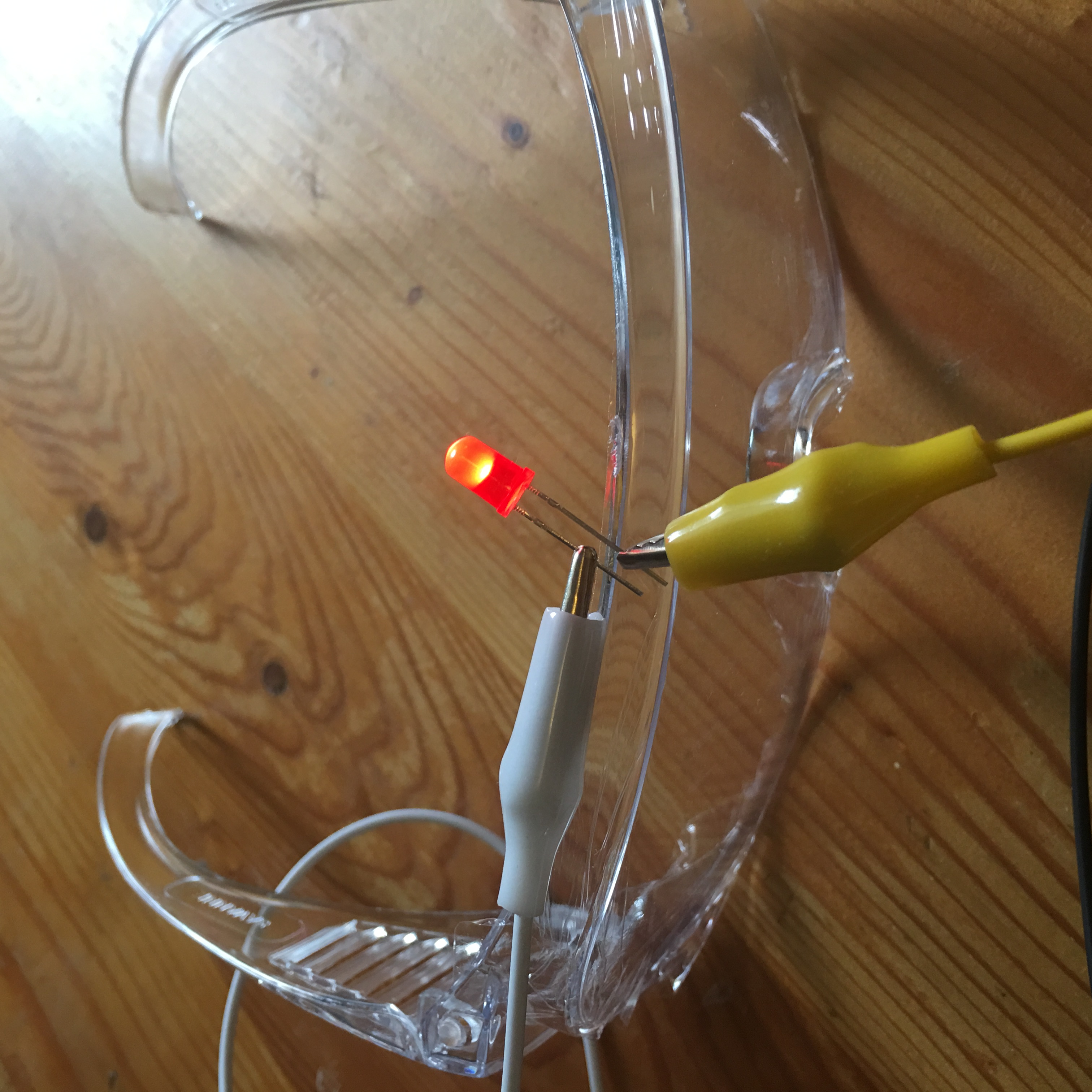
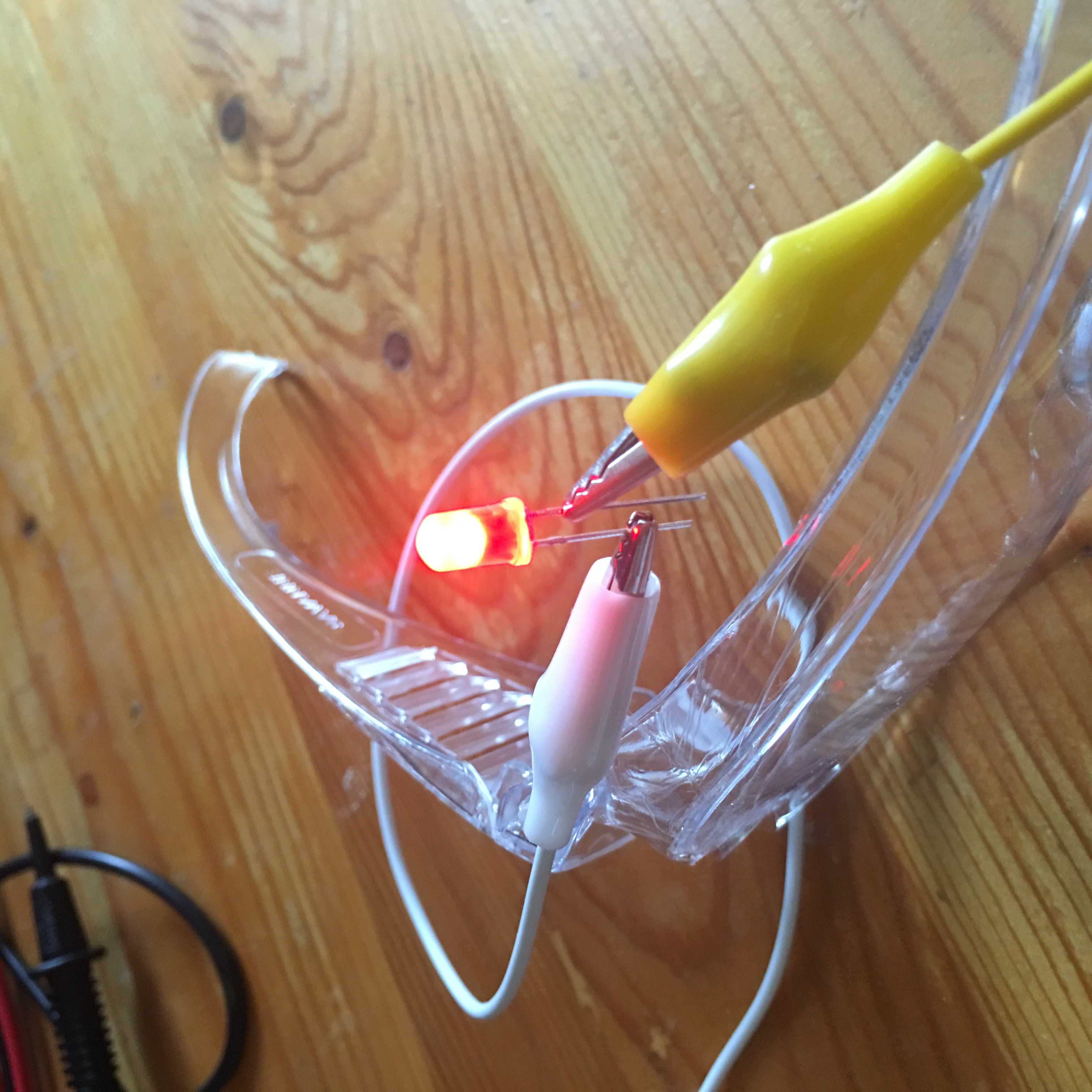
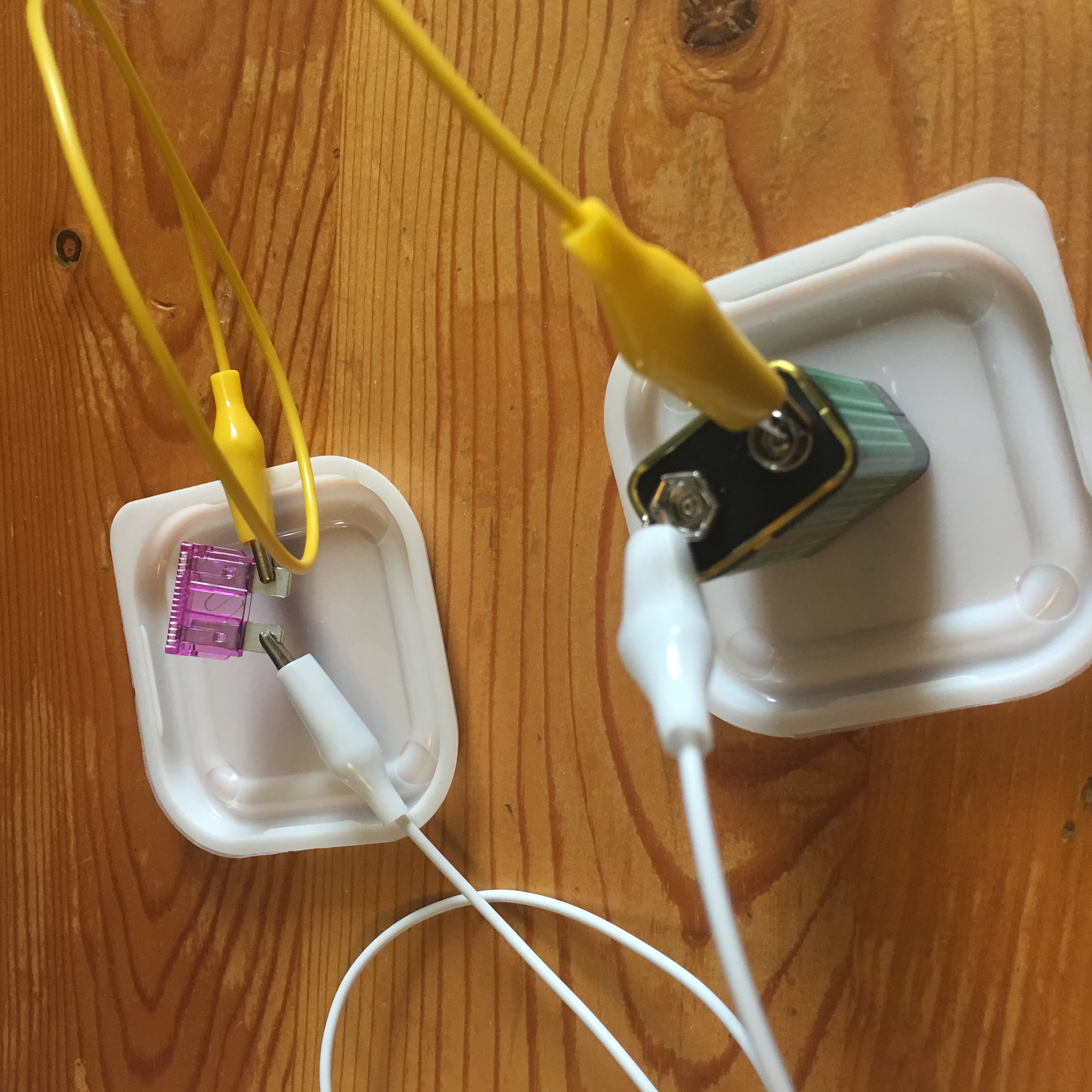
Test circuit using flexible jumper wires                                     Circuit with “hand-made” jumpers
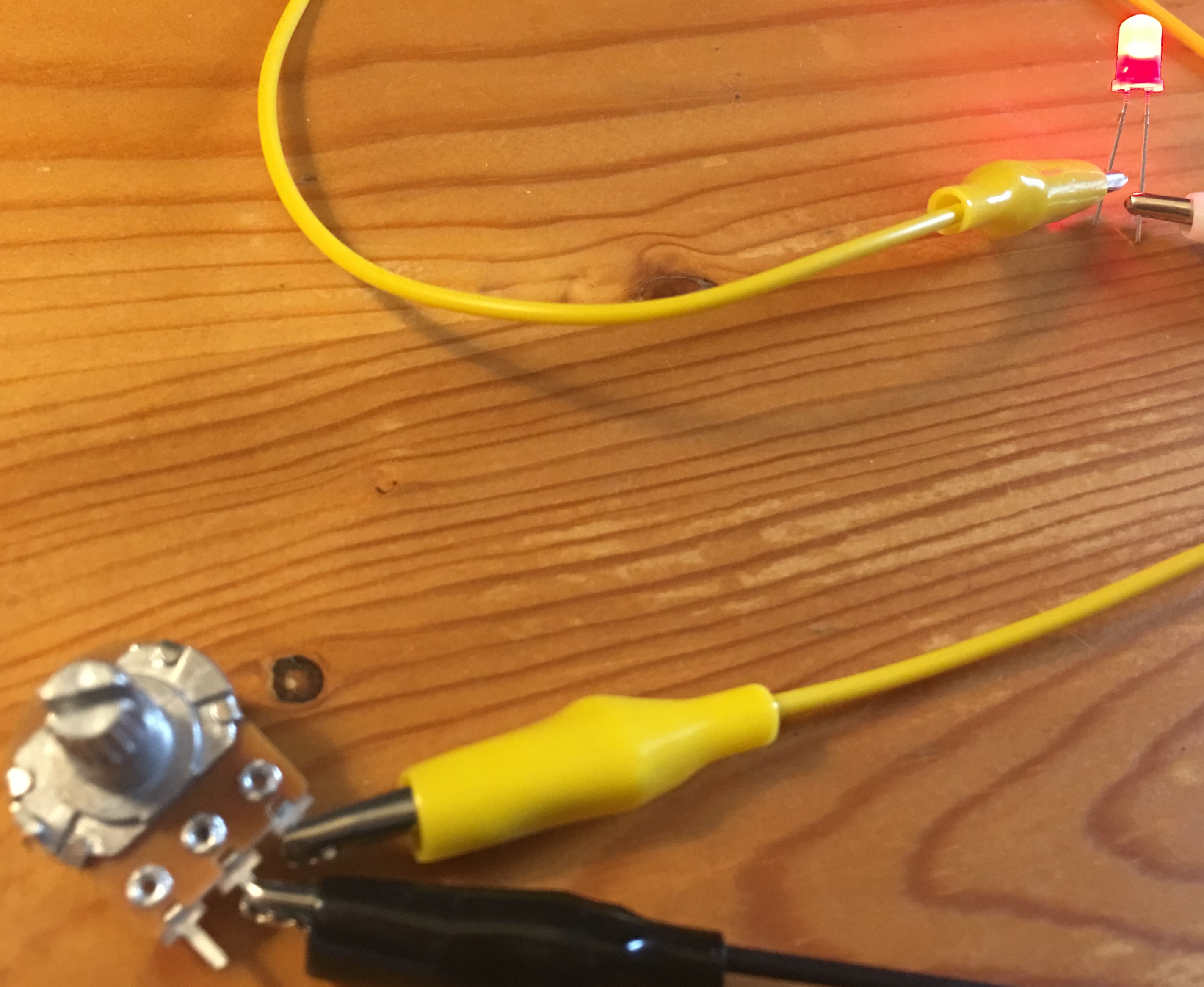
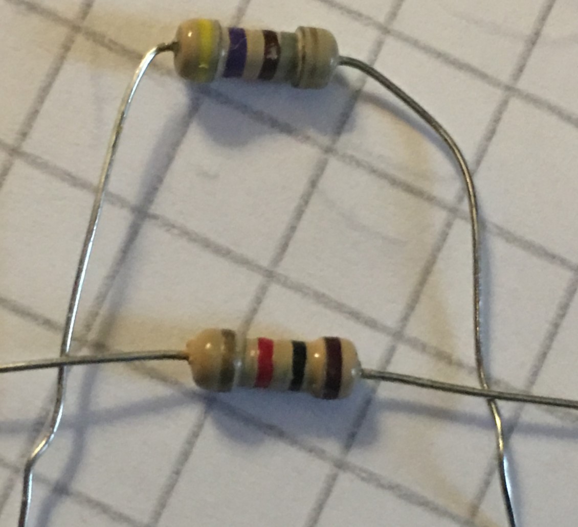
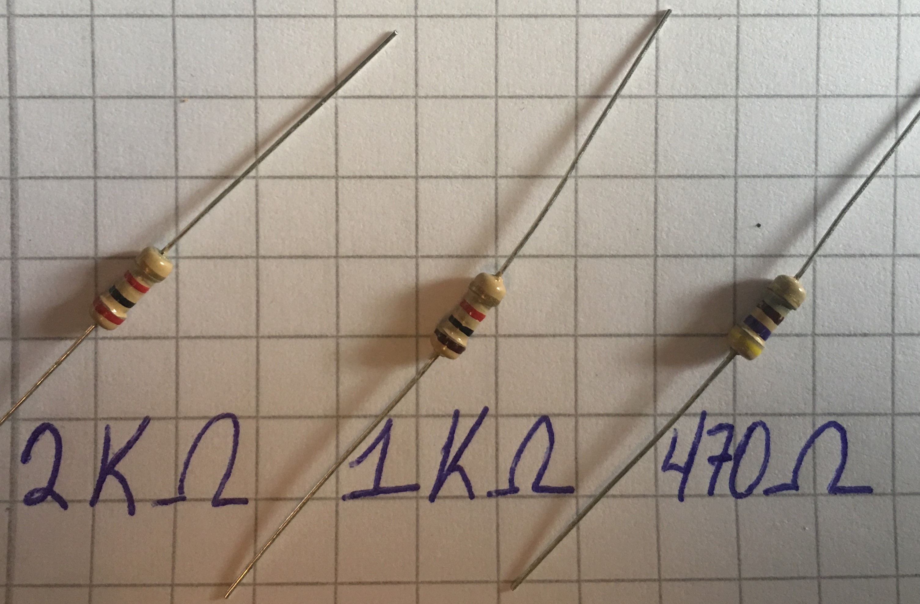
* Making Jumpers

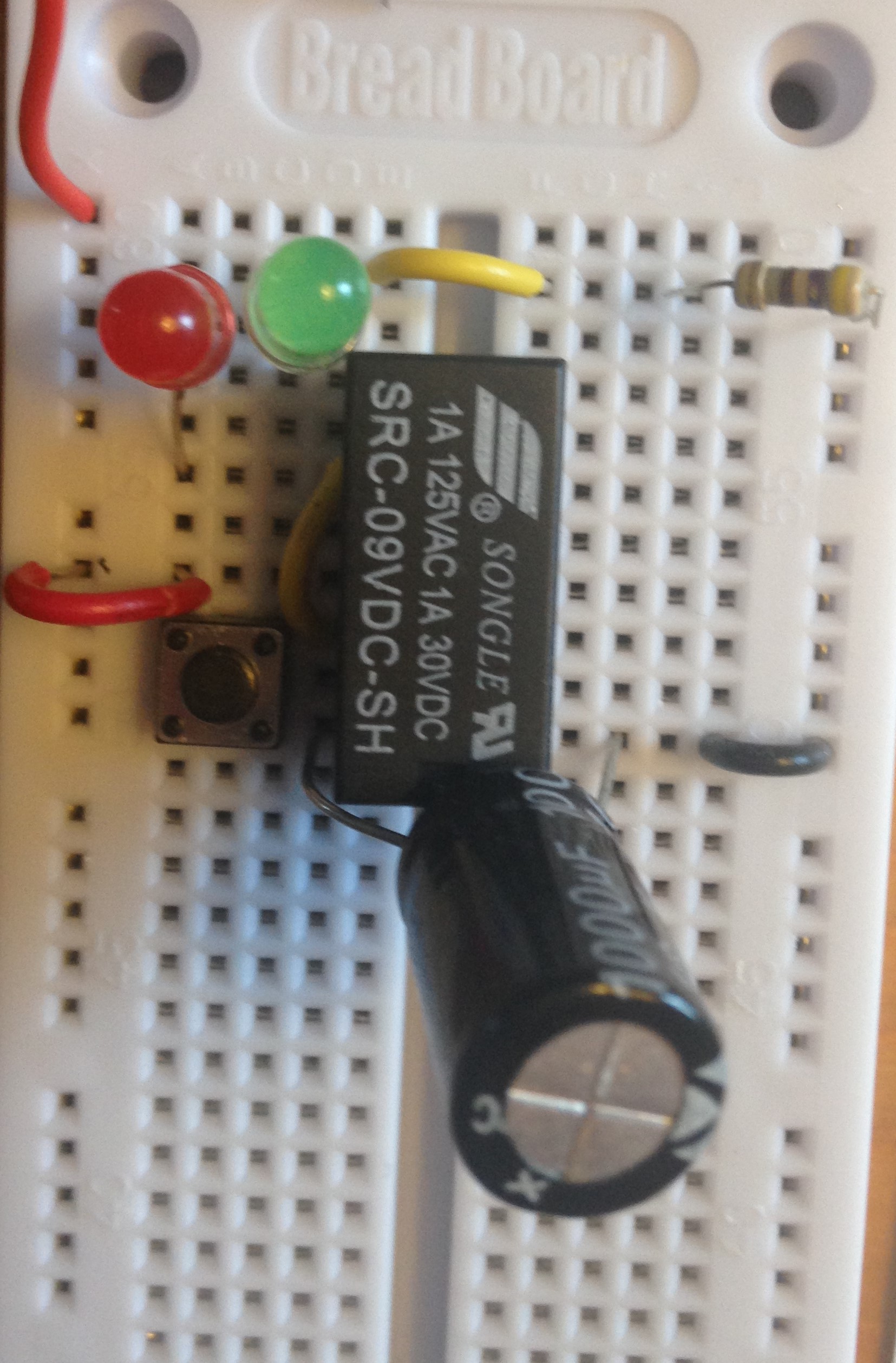
As you can see in the photos above, I first built the circuit shown in Fig 2-62 of the book with flexible jumper wires. This circuit is simple enough that I was still able to easily see the connections between the components. The book explains in greater depth the advantages of using your own hand-made jumper wires in the “Jumpers” subsection from the “Necessary Items for Chapter 2” section.

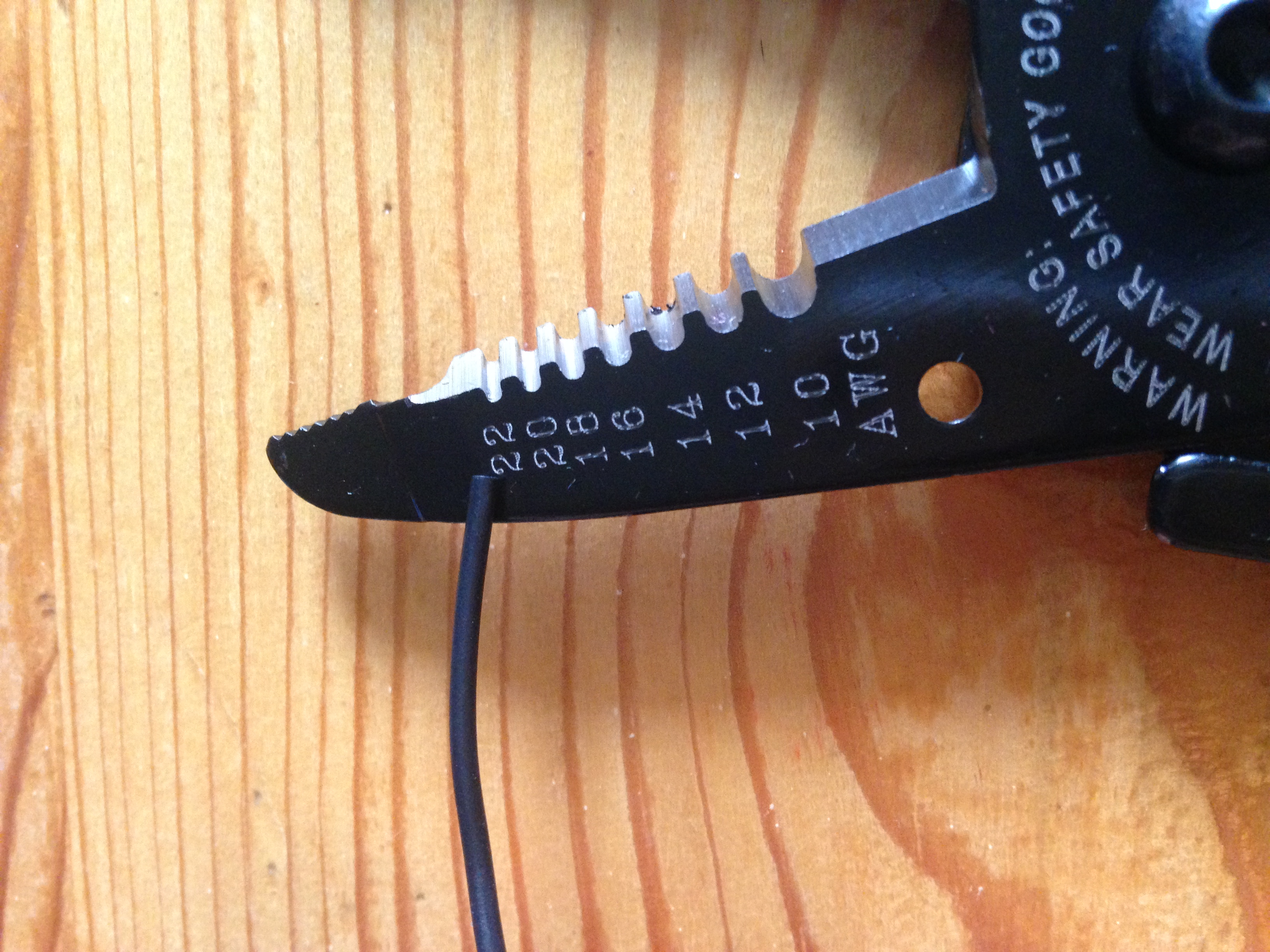
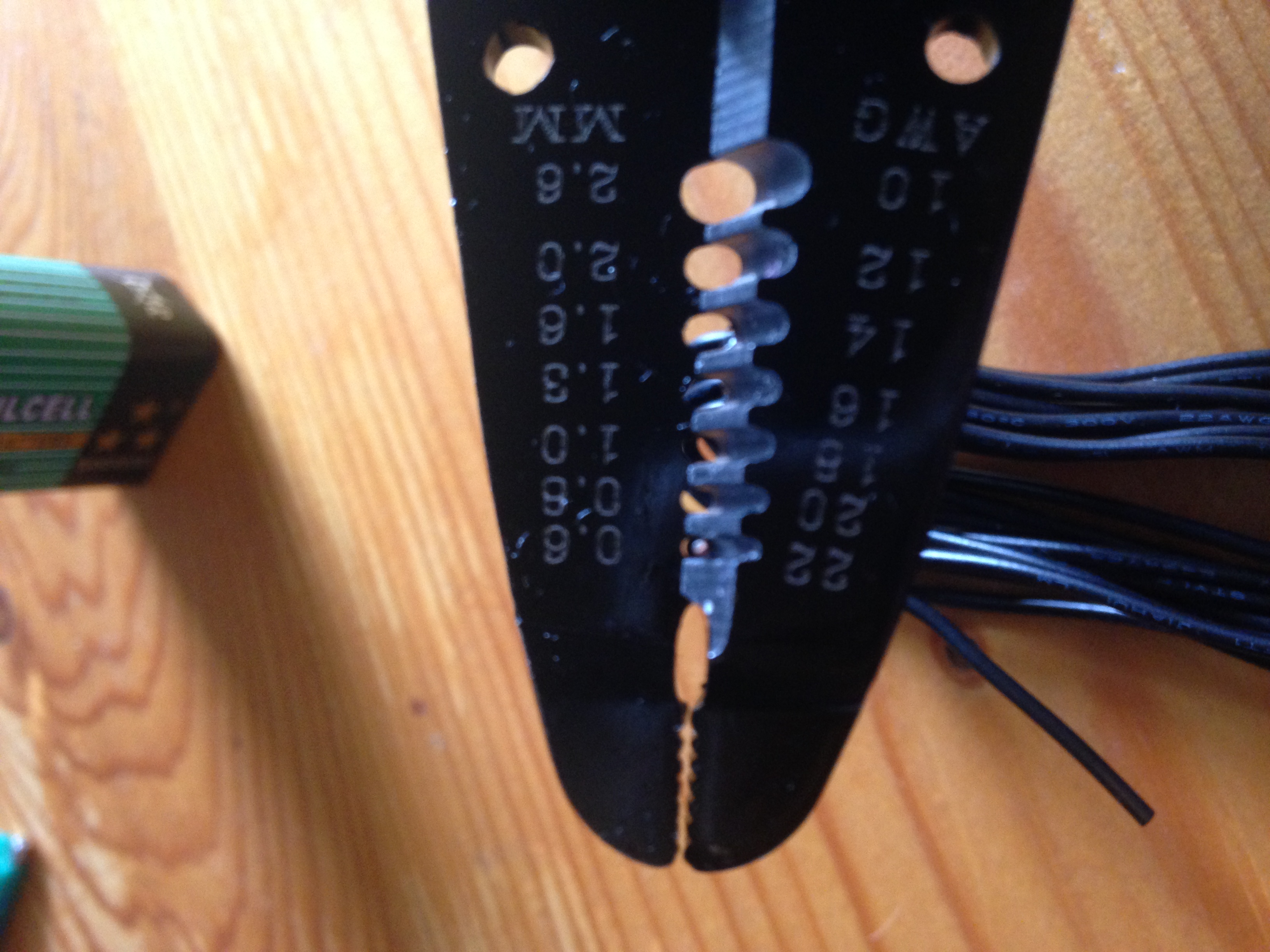
If you want to see pictures showing how to strip wire, check out Experiment 6: Very Simple Switching

Tip: When making your own jumpers, always make them a bit longer than needed. You can always make jumpers shorter, but never longer, well…unless you solder them together, but that’s another story (see Chapter 3 of the book). Also, the extra length helps make them easier to pull out when you need to place them somewhere else.

Be sure to read and fully understand the “Inside the Board” section of the experiment before moving on with the experiment.

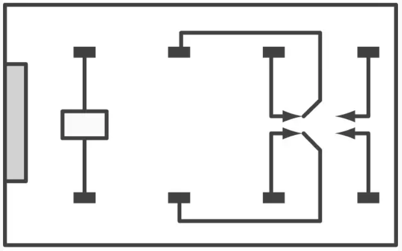
* Relay Circuit, Revealed

A schematic that corresponds with our previously assembled circuit is shown in this section (Figure 2-68). Be sure to understand what every symbol means as well as what’s going on in the circuit.

What path does the current take when the push-button is pressed (closed)?

What path does it take when the button is not being pressed (open)?

* Making it Buzz

Modify your circuit to match the one shown in Figure 2-70 of the book

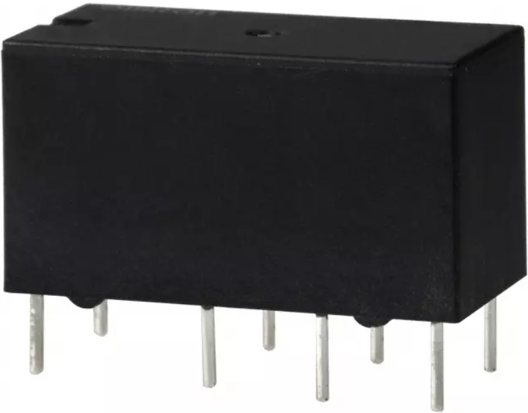
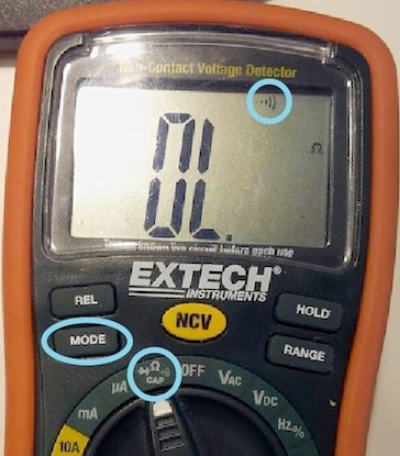
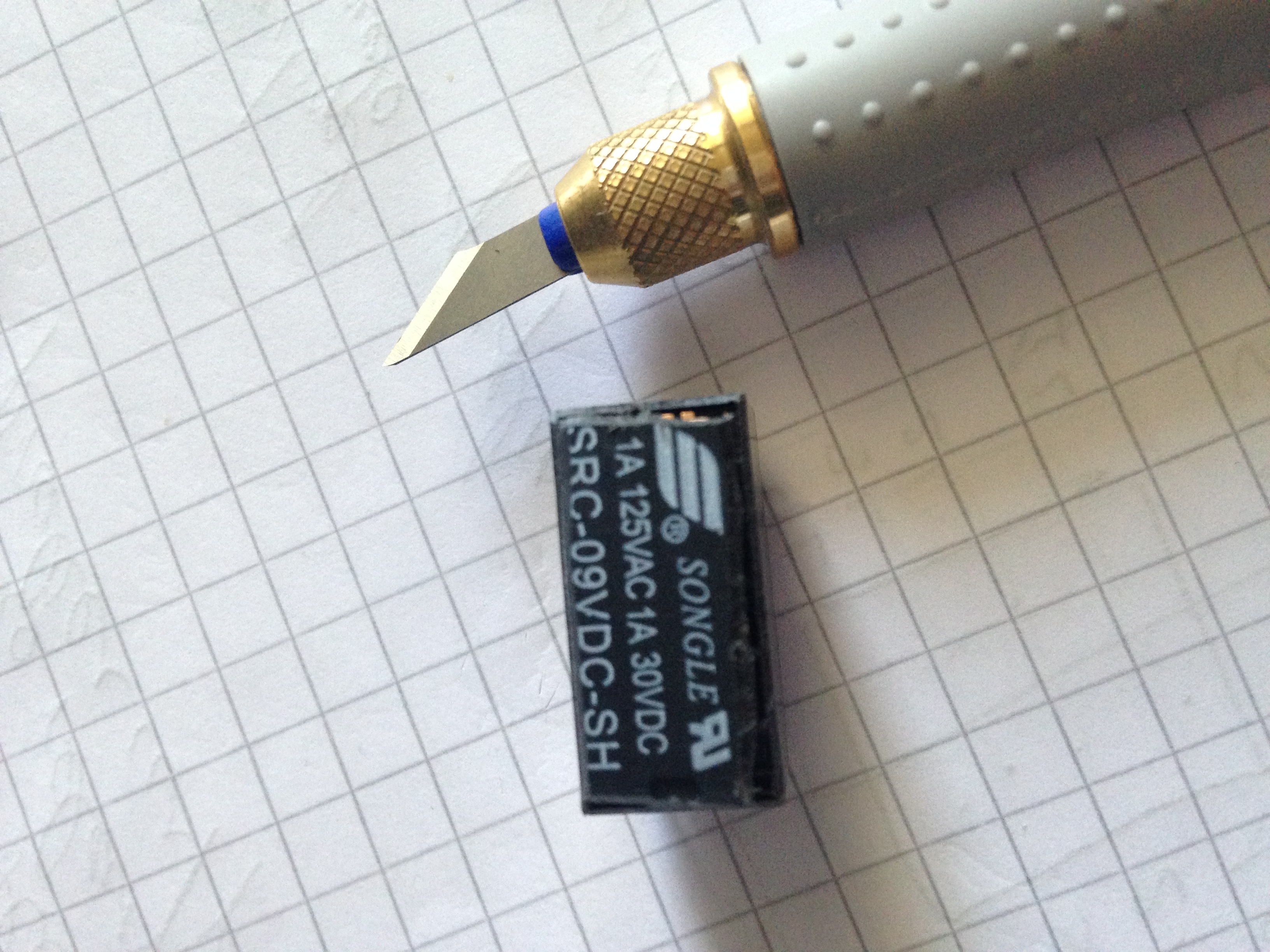
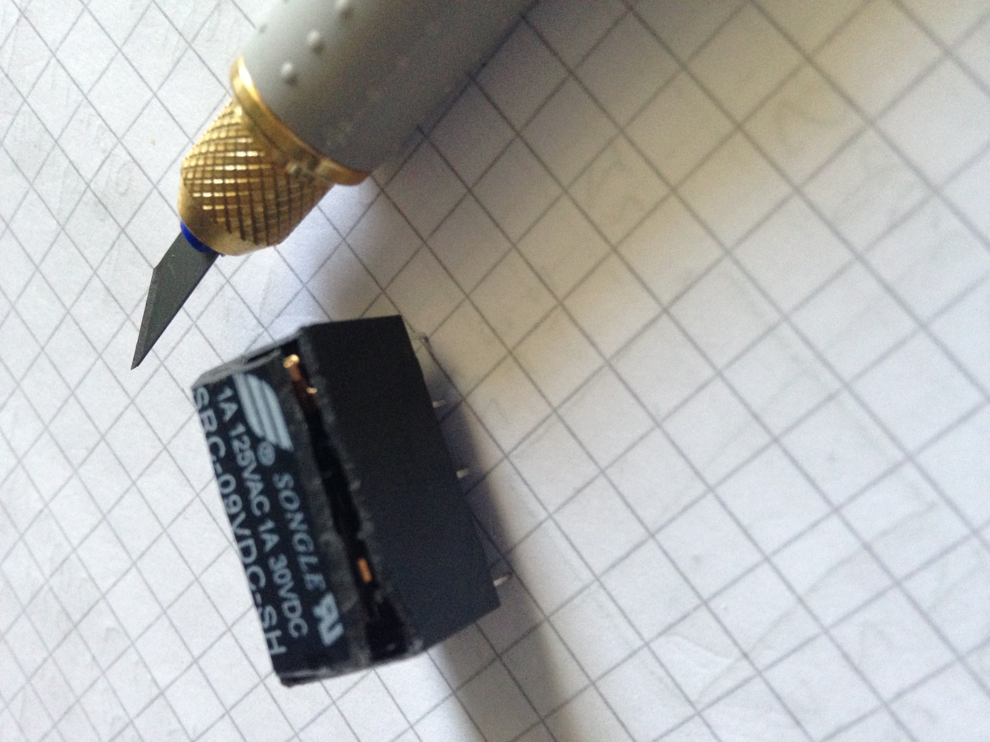
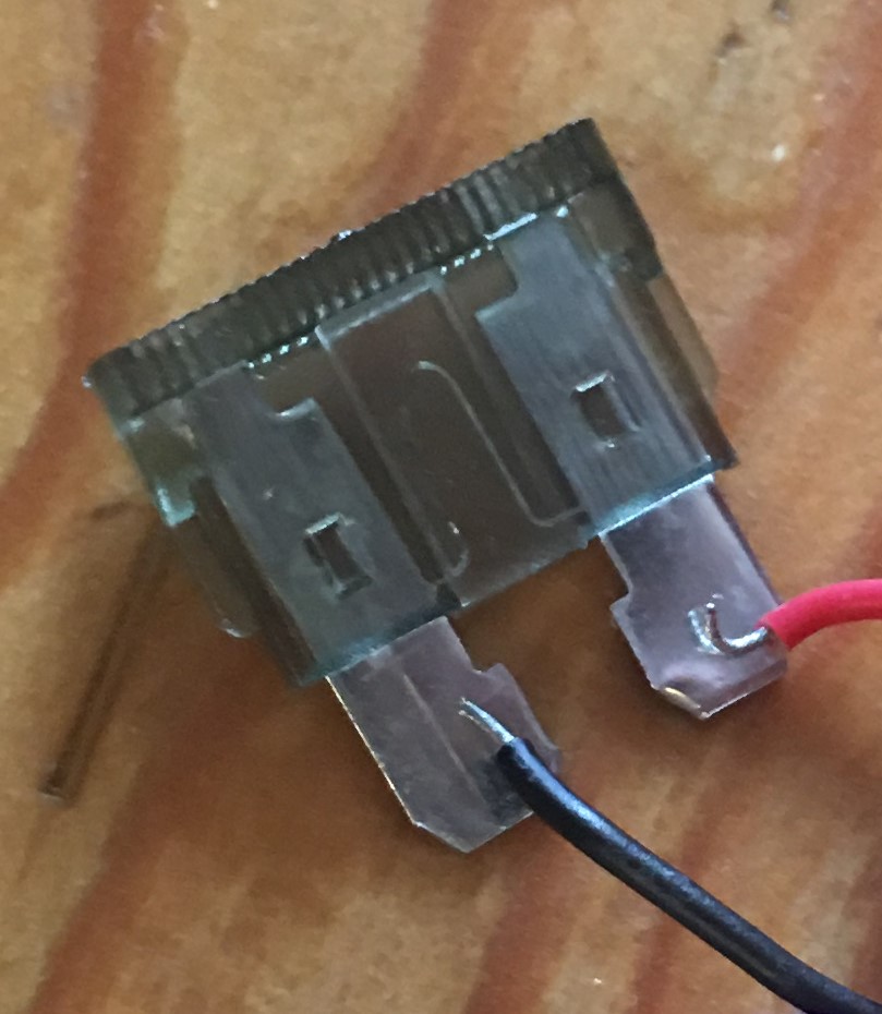
I used my previously opened relay to see if I could notice the oscillation when the button is pressed.

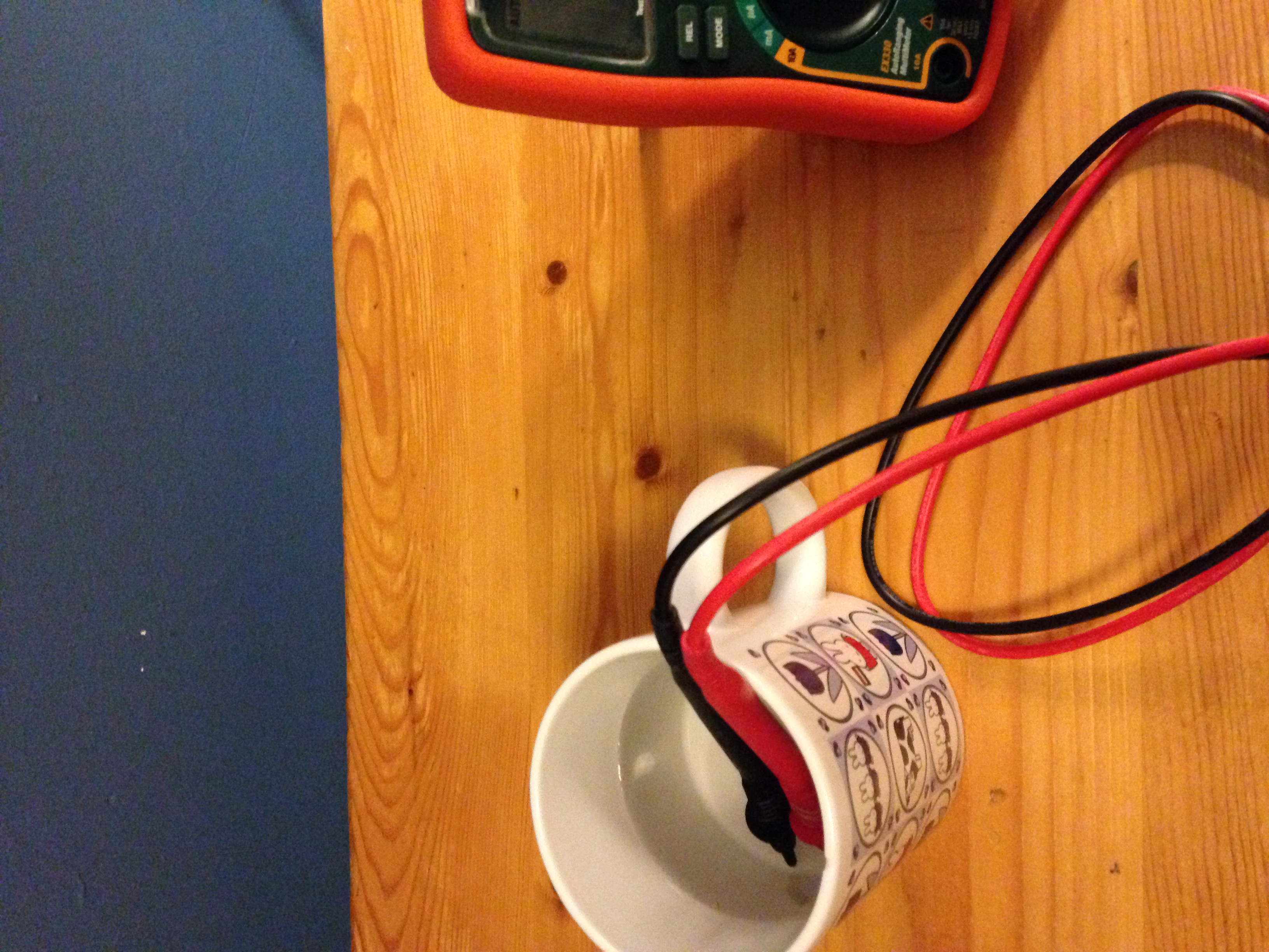
After making the relay buzz a couple of times…nothing happened. I even tested the relay again with both the first setup of this experiment and adding a capacitor but it just wouldn’t work. The relay would make no sound at all when the button was pressed.

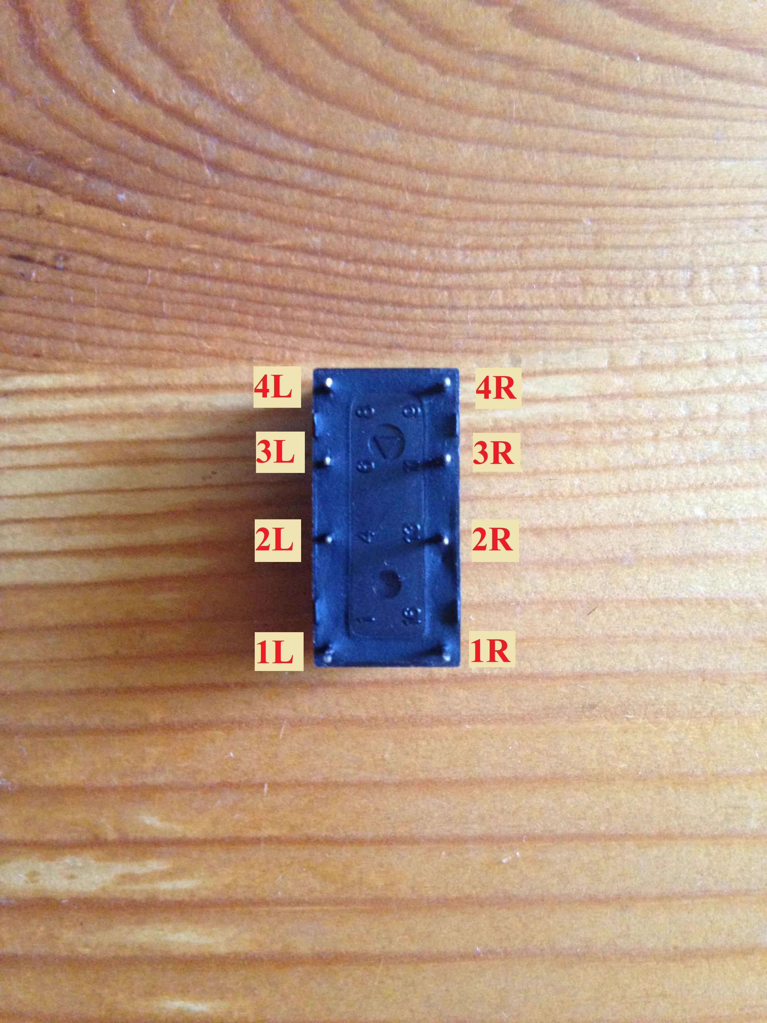
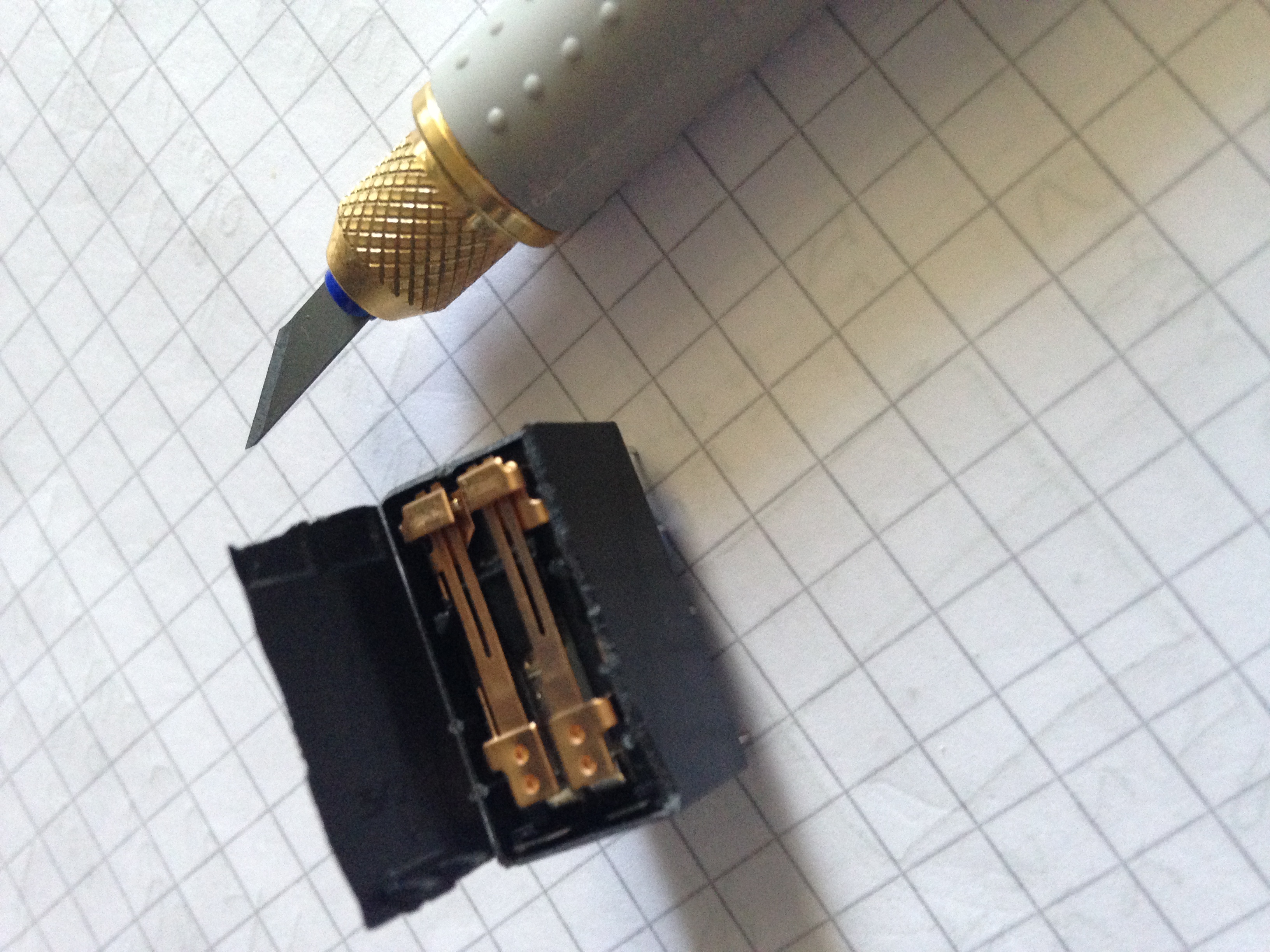
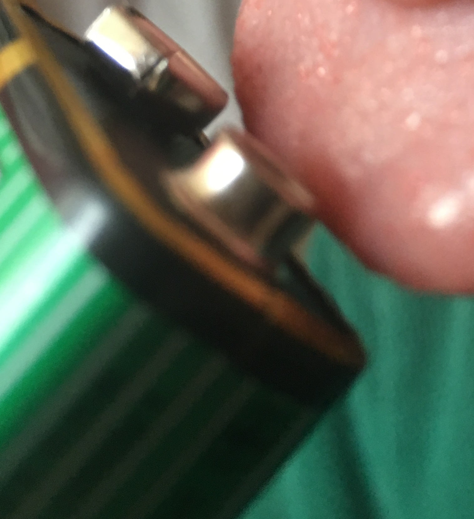
I followed the procedure explained in the “Fundamentals: Fault Tracing” section of the experiment and this revealed that the relay was the problem. It seems the poles got stuck after all that oscillating, this wasn’t hard to fix for the opened relay, for the unopened one, though, I’ll confess I simply waited it out, when I tried to use the relay the next day it was working well again.

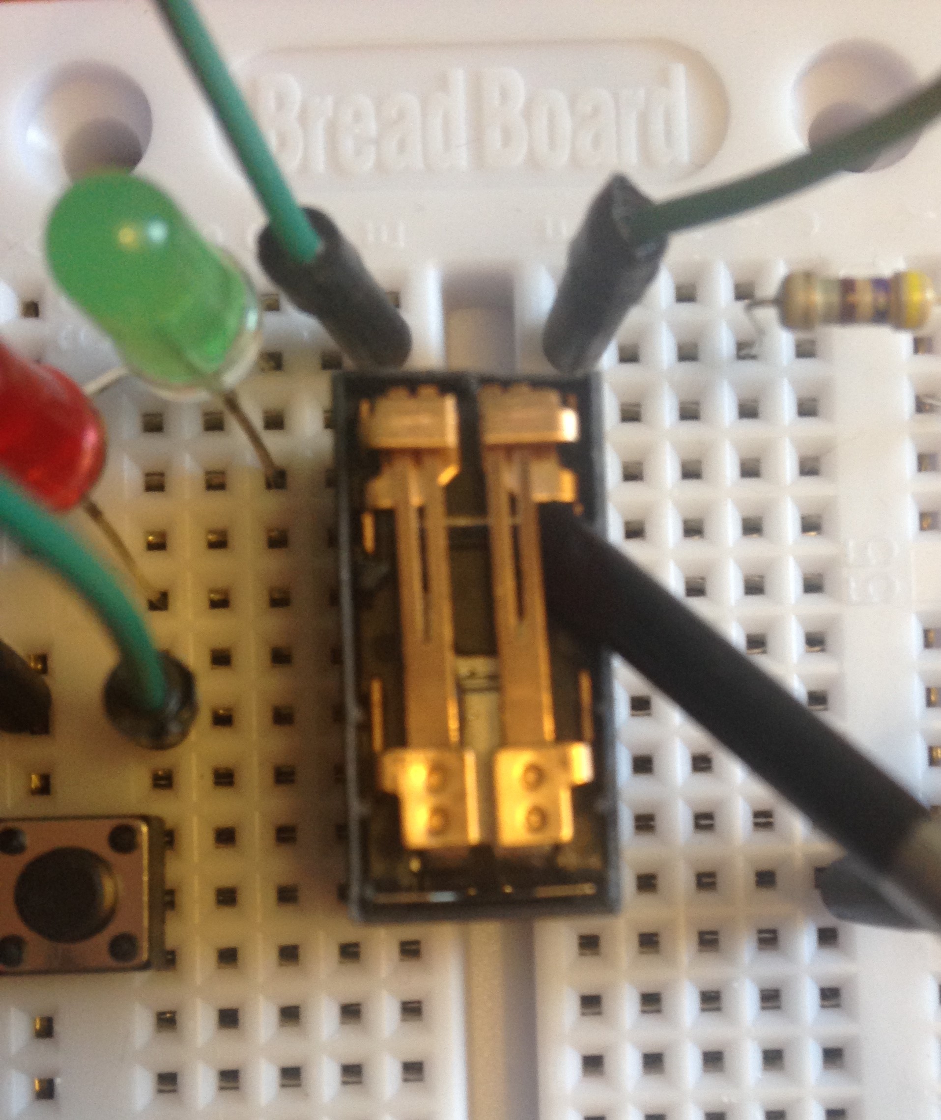
Gently getting the relay unstuck
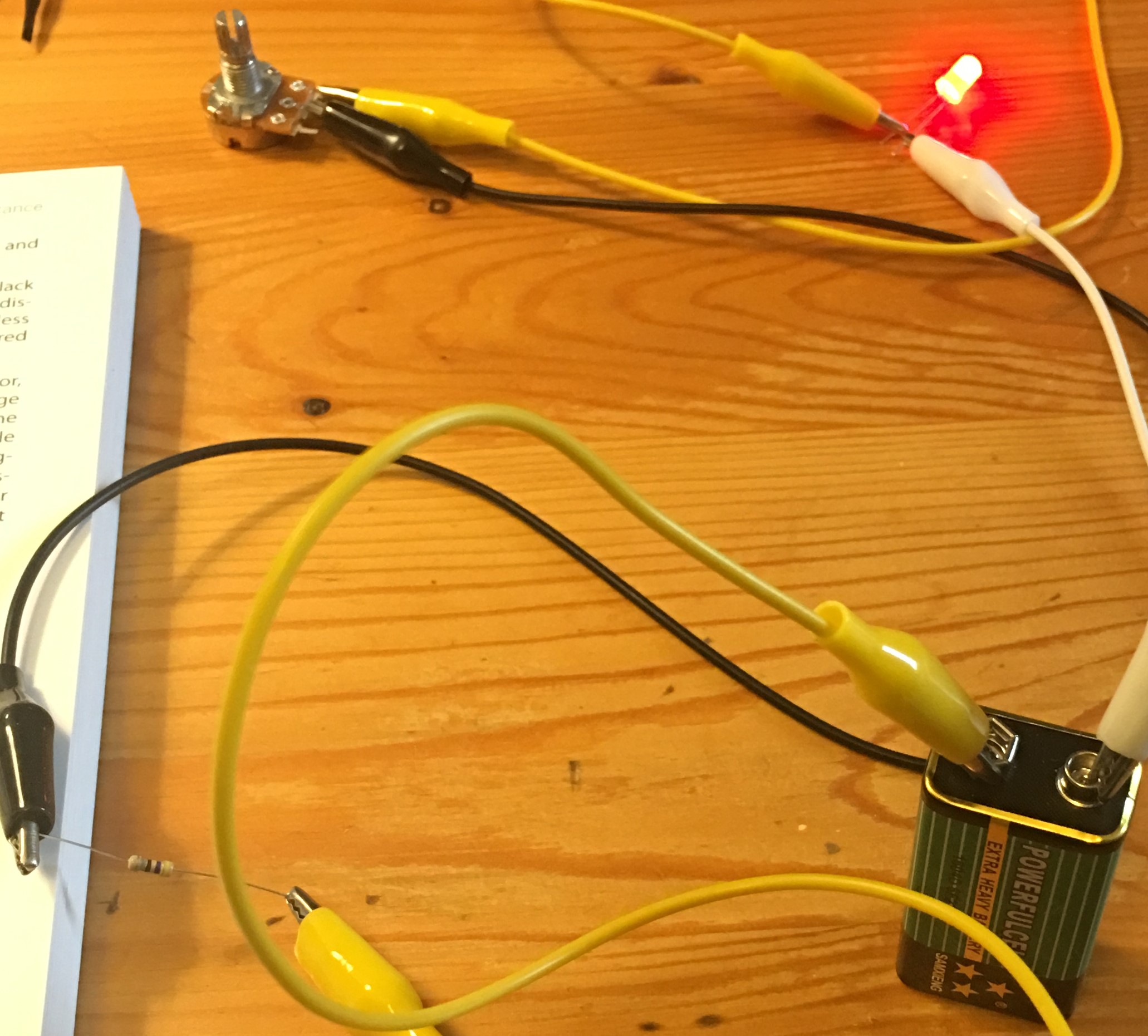
*Adding Capacitance

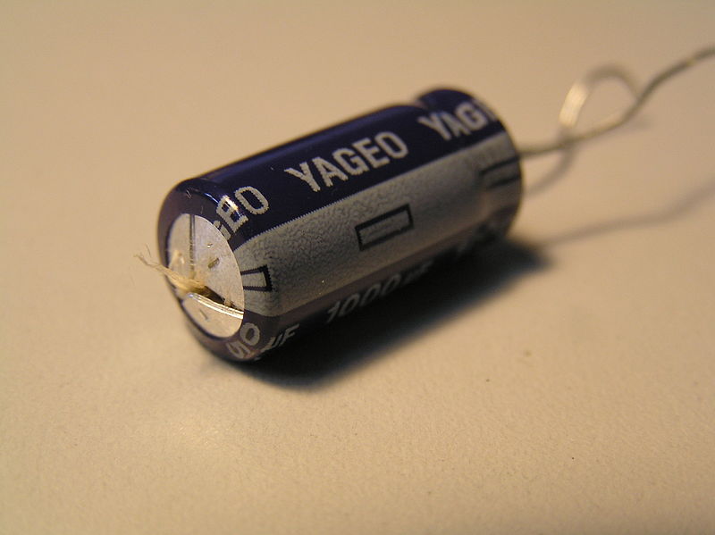
Caution: Electrolytic capacitors are polar components. Connecting them the wrong way can cause them to explode. To learn more about this read the “Caution: Getting Zapped by Capacitance”, “Caution: Observe Capacitor Polarity!”, and “Fundamentals: Fault Tracing” sections of this experiment.

If you would like to actually see a capacitor explode, you can check out William Osman’s awesome video which shows this in slow-mo.

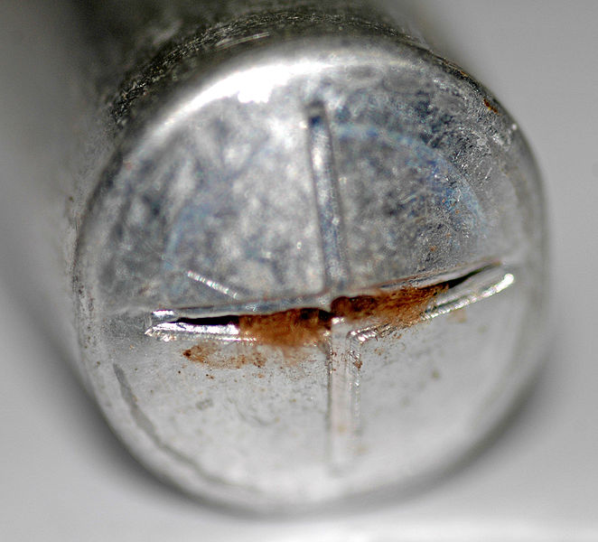
Electrolytic capacitors have a relief vent that lets gases and the dielectric escape in case of failure. 

If you notice the vent in your capacitor is no longer flat (closed), disconnect it from the power supply, wait until it’s cool enough to touch and remove it from the circuit.

ONLY YOU can prevent forest fires… caused by inadequately used electrolytic capacitors

Back to the experiment:


Experiment 7: Investigating a Relay

Time to re-lay the groundwork for all of our subsequent experiments!

* The Relay

The “Necessary Items for Chapter Two” section, at the beginning of chapter two, the book recommends some relay models with the same pin functions as the one used by Mr. Platt.

Pin functions


One of them is the Omron G5V-2-H1 DC9 (Figure 2-20 of the book). You are also to use a relay that does not require polarity and is nonlatching.

But, how can you find out if your relay has these specs? You check the datasheet!

The Omron G5V-2-H1 DC9, for example, has the Digikey part number Z3673-NDYou can see the relay’s specifications on the Product Attributes table. The Coil Type is specified as Non Latching, which is what we want.

To check the coil polarity we should check the relay’s datasheet


Page 4 shows the dimensions and terminal arrangement of the relay.

The pin spacing and internal connections of the relay match those from Figure 2-21 of the book.

Below the Bottom View of the Terminal Arrangement/ Internal Connections you see between parentheses that there is no coil polarity

So the Omron G5V-2-H1 DC9 matches all of our requirements!

Test Yourself! Look for the datasheets of the other relay’s recommended by Mr Platt and confirm they match the specifications required.


* Procedure

Don’t confuse the faint click of the relay with the click of the pushbutton.

Touch the relay’s body if needed, so you can “feel the click” when you press the pushbutton and the contacts in the relay open and close.

Testing the continuity between two contacts

I’m ready for my close-up

It was tricky to hold the multimeter’s probes against the relay’s contacts while trying to press the pushbutton, which is why I used test leads as shown in Figure 2-51 of the book.

Test the continuity between several contacts both when pressing and not pressing the pushbutton.


If you don’t know how to measure conductivity with your multimeter be sure to check its manual. If your multimeter is the EXTECH’s EX330, set you meter’s dial to measure continuity and then click the MODE button several times until you see the continuity symbol on the multimeter’s screen.

Testing for Conductivity:

Here are my results!

Pushbutton pressed

2R and 3R

No conductivity

2R and 4R

Conductivity

3R and 4R

No conductivity


Pushbutton not pressed

2L and 3L

Conductivity

2L and 4L

No conductivity

3L and 4L

No conductivity

But what about testing the conductivity between the contacts on the left and right sides of the relay?

Feel free to try, but there’s no conductivity whatsoever between the left and right sides of the relay.

To understand why, read the “What’s Going On Inside” and “Other Relays” sections of the experiment. Can you now better understand how your relay works? There’s no conductivity between the left and right contacts of the relay because they’re two different poles!


* Opening It Up

Be sure to always move the knife away from you. Work slowly and be patient.

It’s not a sprint, if you get tired, ask for help and make it a relay!  ☺

Don’t shave the edges of the plastic shell any more than you have to, so you can continue using this relay in later experiments.

Connect the relay again, this time, when you press the pushbutton and current passes through the coil, you will be able to see the insides of the relay moving.

Lastly, read the “Fundamentals: Relay Terminology” section of the experiment.

Practice looking for the all the terms introduced in this section of the book for the Omron G5V-2-H1 DC9

Hint: The switching capacity is specified for a resistive load.


Learning how to find components with the right specifications is an essential skill that will help you save time and money as you move forward with your learning.


Experiment 6: Very Simple Switching

Chapter 2 is upon us!

* Fundamentals: All About Switches

Note: My switches end in solder lugs, not screw terminals, so I followed Mr. Platt’s advice and used alligator test leads to connect the components together. If you’re in a similar situation, use test leads of different colors so it’s easier to see what parts are connected together.


Switch with solder lug terminals


Switch with screw terminals


To see what other types of lugs a toggle switch can have, visit the Toggle Switch section of the Digikey website and scroll through the Termination Style section. If you select one and click Apply Filters, you’ll be shown switches with only that kind of termination style. Look at the pictures, when do you think each kind of terminal type would be most useful?

https://www.digikey.com/short/j90bh4


The book introduces several configurations of switches, you can see these in the Circuit section, see how many you can recognize from the book!

https://www.digikey.com/short/j90bh4


Don’t worry about not knowing what all the specifications of the switches on the website mean. The book introduces the most important ones gradually (the ones you actually need to know about to make the experiments). The world of electronics is vast, so relax and enjoy the ride!


If you have a toggle switch with screw terminals and will use hookup wire to create the connections, be sure to use a wire stripper for the right wire gauge. While you don’t need to use 22-gauge hookup wire to make the connections for this experiment, this wire gauge will be needed for almost all of the experiments from Experiment 8 onward, so it would be wise to just buy hookup wire with 22-gauge from the get go.


Determine the wire-gauge of your wire, then place the wire between the teeth of the wire stripper and pull the stripper away from the wire while your other hand holds the wire tightly, the insulation of the wire will slide off without damaging the conductor underneath.


Gentlemen, switch on your LEDs!


Alligator clips are bulky, so be very careful that they’re only touching the lug they’re supposed to be touching and not nearby lugs or alligator clips (I’m only talking about the metallic clips, of course, not the plastic boots). If a metallic clip touches another clip or lug, you’d creating an extra connection, which means the results of the experiment won’t reflect the way a properly connected switch works, which is the goal of the experiment.


Observation: With the current setup, if the LED is on, toggling either of the switches’ poles will turn the LED off and vice-versa.

But, why is this so?

This question takes us to the next section of the experiment where we’ll learn about what’s going on inside our switches.


* Checking Continuity

Set your meter’s dial to measure continuity

If you’re unsure about how to measure continuity with your multimeter, read your multimeter’s manual. The EXTECH’s EX330 requires you to set you meter’s dial to measure continuity and then click the MODE button several times until you see the continuity symbol on the multimeter’s screen.


Now all you need to do is touch a different terminal with each of the probes to see if they’re connected.

Toggle pointing left

Terminals 1 and 2

No conductivity

Terminals 1 and 3

No conductivity

Terminals 2 and 3

Conductivity


Toggle pointing right

Terminals 1 and 2

Conductivity

Terminals 1 and 3

No Conductivity

Terminals 2 and 3

No Conductivity


Read carefully through the theory presented in the Introducing Schematics and following sections of the experiment and compare our results from the functioning of a single switch to the schematics showing our previously assembled circuit.


Inside a SPDT switch

Now that you know which terminals are connected together when the toggle is pointing to either side, look at Figure 2-37 of the book and study how the circuit is altered whenever you toggle either of the switches’ poles.


Experiment 5: Let’s Make a Battery

It’s time for the last experiment of Chapter 1


I found some really cheap L-shaped 1in. Zinc-plated steel brackets at my local hardware store.

I was unable to light up the LED with this setup

Luckily I found some small plastic containers at a dollar store and was able to imitate Mr. Platt’s second setup. This setup delivers more voltage since we’re connecting more pairs of electrodes (brackets and pennies) in series.

Shine bright like a LED!

The highest voltage reading with this setup was 3.8V, which is higher than I was expecting. So be sure to measure the voltage of your circuit before connecting the LED to it. If the voltage measured is higher than the Max Forward voltage of your LED (check its datasheet), you could end up with another burnt LED like in experiment 4, or would you?

Turns out that while it is a bad idea to apply more than the recommended forward voltage to an LED, a lemon battery may be unable to sustain a voltage when it has a load applied to it (such as an LED). It would then be interesting to measure the voltage of the lemon battery with and without the LED attached (the voltage drops significantly when you add the LED).

The current is also important, the internal resistance of a battery limits current, and current is the main factor burning out an LED.

For these reasons, it’s safe to say you won’t end up with a burnt LED  when you connect it to our lemon battery!

The Voltage eventually settled at 2.1V

Be sure to carefully read through the theory section of this experiment. A basic understanding of the relationship between voltage, current, and resistance will greatly help your understanding of electricity and how and why circuits are formed.

To keep your test leads in good shape, clean them with soap and water then quickly dry them to avoid rusting.

Time for Chapter 2!


Experiment 4: Variable Resistance


* Look Inside Your Potentiometer

Here are some photos from different angles of the potentiometer I used (before prying it open):

Time to open it up!

* Testing the Potentiometer

Middle and Right terminals

Resistance

Min. Resistance (shaft fully turned clockwise)

2Ω

Max. Resistance (shaft fully turned counterclockwise)

1.036KΩ


* Dimming Your LED

The LED that wouldn’t die

I did NOT manage to burn the LED. I even connected it directly to the 9V battery but it just refused to burn.

Still, it was fun to play with the potentiometer, turning the knob and watching the LED’s brightness change as less and more current goes through it. A potentiometer isn’t polar so the LED would light up no matter which test lead was connected to which of the potentiometer’s terminals.


Center and Right terminals. As you turn the shaft clockwise, the LED shines brighter.

Center and Left terminals. As you turn the shaft counterclockwise, the LED shines brighter.

Protecting the LED with a resistor

* Measuring Potential Difference

Middle and Right terminals

Voltage

470Ω resistor

Voltage

1KΩ resistor

Min. Resistance (shaft fully turned clockwise)

24.4mV

13.5mV

Max. Resistance (shaft fully turned counterclockwise)

4.57V

3.530V

Measuring potential difference across an LED and a resistor

Middle and Right terminals

LED

470Ω resistor

Min. Resistance (shaft fully turned clockwise)

2mV

5.84V

Max. Resistance (shaft fully turned counterclockwise)

1.907V

2.049V


* Checking the Current

Multimeter between the LED and Potentiometer

Current

Min. Resistance (shaft fully turned clockwise)

12.48mA

Max. Resistance (shaft fully turned counterclockwise)

4.39mA


Multimeter between the battery and LED

Current

Min. Resistance (shaft fully turned clockwise)

12.30mA

Max. Resistance (shaft fully turned counterclockwise)

4.32mA


* Making Measurements

Multimeter between the potentiometer and battery (no LED)

Current

Min. Resistance (shaft fully turned clockwise)

8.50 mA

Medium Resistance (shaft turned halfway)

6.33mA

Max. Resistance (shaft fully turned counterclockwise)

4.25mA


* Fundamentals: Series and Parallel

Two resistors in parallel (R1= 470Ω, R2= 1KΩ) offer an equivalent resistance of 319.73Ω

Of course, the measurements won’t always be what we expect, this due to the fact that each component has a tolerance range, so, for example, a 1K resistor with a 5% tolerance may offer a resistance that is 5% away from 1K. The reading my multimeter gave of the two resistors in parallel shown in the picture above was 318.8Ω.


Experiment 3: Your First Circuit

It’s time, people, time to light up some LEDs!!!

* Lighting an LED

So, the thing is, I didn’t have a 2.2KΩ resistor at hand, as you can see in the picture above, (now that you know how to decode the value of resistors from the Fundamentals: Decoding Resistors section).

My resistor is Red Black Red Gold = 2 0 2 5% = 2000 Ohms with a 5% tolerance.

A 2.2K (2000) resistor would show the colors Red Red Red Gold = 2 2 2 5% = 2200Ω, 5% tolerance.

Still, the Resistor is still perfectly usable for the educational lesson the experiment wishes to transmit, which is: How does resistance affect current?

Here are the other resistors that will be tested:


So, let’s begin!

It’s alive!!!…..ever so slightly.

Circuit with a 2KΩ resistor                               Circuit with a 1KΩ resistor   

 Circuit with a 470Ω resistor


As the resistance is decreased (by changing the resistor) the LED shines more brightly since more current is going through it!


* Checking a Resistor

These are the values the color coding of each resistor translates into.

The first resistor is 2KΩ (and not 2.2kΩ). The multi-meter shows a value of 1.993KΩ which is within the tolerance specified by the golden stripe (5%).


Experiment 2: Let’s Abuse a Battery!

Before we begin, for those who might be thinking of ignoring Mr. Platt’s advice and want to see what happens when you short a lithium battery, just watch this AWESOME video instead.


*Generating heat with current

The battery and cables will get hot!


It didn’t happen as fast as I thought it would, though.

Don’t worry as long as you don’t leave ’em on too long you’ll still be able to touch the cables so you can disconnect/untangle them.


*How to blow a fuse


I used 2 different 1.5V AA brand new batteries but unfortunately, I was unable to blow the 3A fuse (I even tried with a 9V battery).


Luckily I had a 1A fuse at home, which did burn, but only by applying the wires from the battery holder to it directly.


Note: The kits from Protechtrader now include a 1A fuse and the text of the book has been modified to recommend this.

Many people have had trouble blowing a 3A fuse for two reasons:

  1. Some fuses are manufactured differently from others
  2. The wires from a battery holder have been made thinner by companies trying to save a little money, so the wires can’t pass enough current to blow the fuse.

A 9V battery could also not work, because it can’t deliver more current than a 1.5V battery–in fact, a 9V battery just contains 6 little 1.5V batteries in series. So, this is an interesting lesson in voltage vs current. Current is needed to blow a fuse!


To learn more about batteries and fuses you can also check out Mr. Platt’s Encyclopedia of Electronic Components Vol. 1 Chapters 2 and 4


Experiment 1: Taste the Power!

The first challenge in the book is to lick a 9V battery. Why is it a challenge, you ask?- Try it!

I’ve read some other people’s accounts of this experiment in which they say they barely felt anything, but oh did I feel it!

01

After drying my tongue it was less uncomfortable, but still perfectly detectable.

* Measuring Your Tongue

My multimeter’s readings were both higher than what the book suggested they would be.

I did get the experiment’s conclusion that the lower resistance of my moist tongue allowed more current to flow through it and that’s why the sensation was weaker when my tongue was dry.

Tongue

¾ in (1.905 cm)

Moist

609KΩ

Dry

740KΩ


* Further Investigation

My arm

¼ in (0.635 cm)

1 in (2.54 cm)

Dry skin

No reading/ L

No reading/L

Moist skin

.97Ω

1.06Ω

Mark your arm so you know where to place the probes.

04

The added salt dramatically diminished the resistance!

Glass of water (1cup)

2/3 in (1.69 cm)

Without added salt

1.190MΩ

With added salt (3 gr.)

11.5KΩ


Materials

Everything you will need to perform the experiments is detailed in the “Tools, Equipment, Components, and Supplies” section of the book.

In addition to this, the materials needed for the experiments from each chapter will be mentioned at the beginner of the chapter.  The materials needed for each experiment will also be listed at the beginning of each experiment.


Buying a lot of components can be overwhelming for a beginner, which is why you can also buy kits with all of the components you need. I bought the 3 kits offered by ProTechTrader and I can honestly say I’m truly happy I did. There’s no electronics shop where I live so I would have had to order all of the components online which, if you don’t know what you’re doing, can get very time consuming and expensive if you order the wrong parts.

The people from ProTechTrader answered all of my questions about the kits. They’re in touch with Charles Platt so the components included in the kits are truly those you need. ProTechTrader also offers a kit for Charles Platt’s latest book: Easy Electronics.

Everything comes very neatly packaged and labeled!


If you have already a lot of the components needed for the experiments at home, then you can buy those you need from websites like Digikey.

They have a very cool website that allows you to efficiently filter components so you can find exactly what you’re looking for (They also sell tools!). They also offer a lot of cool free online tools and media. Be sure to check their “Resources” section.

I’ve included links to components listed on the Digikey website that one could use for each experiment. These are not exactly what one must buy for an experiment to work, but rather are meant to serve as examples.


Both ProTechTrader and Digikey provide great Customer Service. Don’t be afraid to explore their websites!


About the author: Charles Platt


Charles Platt is an author, prototype designer and former
computer programmer.

He is currently a contributing editor to Make magazine, which has published more than 50 of his articles. Six of his books are available from MakerMedia:


Make: Electronics, an introductory guide, now available in its second edition.


Newest book! Easy Electronics, a prequel to Make: Electronics which requires no tools and a very low amount of parts.

Fun for the whole family!


Make: More Electronics, a sequel that greatly extends the scope of the first book.


Encyclopedia of Electronic Components, volumes 1, 2, and 3 (the third written in collaboration with Fredrik Jansson).


Make: Tools, which uses the same teaching techniques as Make: Electronics to explore and explain the use of workshop tools.