Experiment 5: Let’s Make a Battery

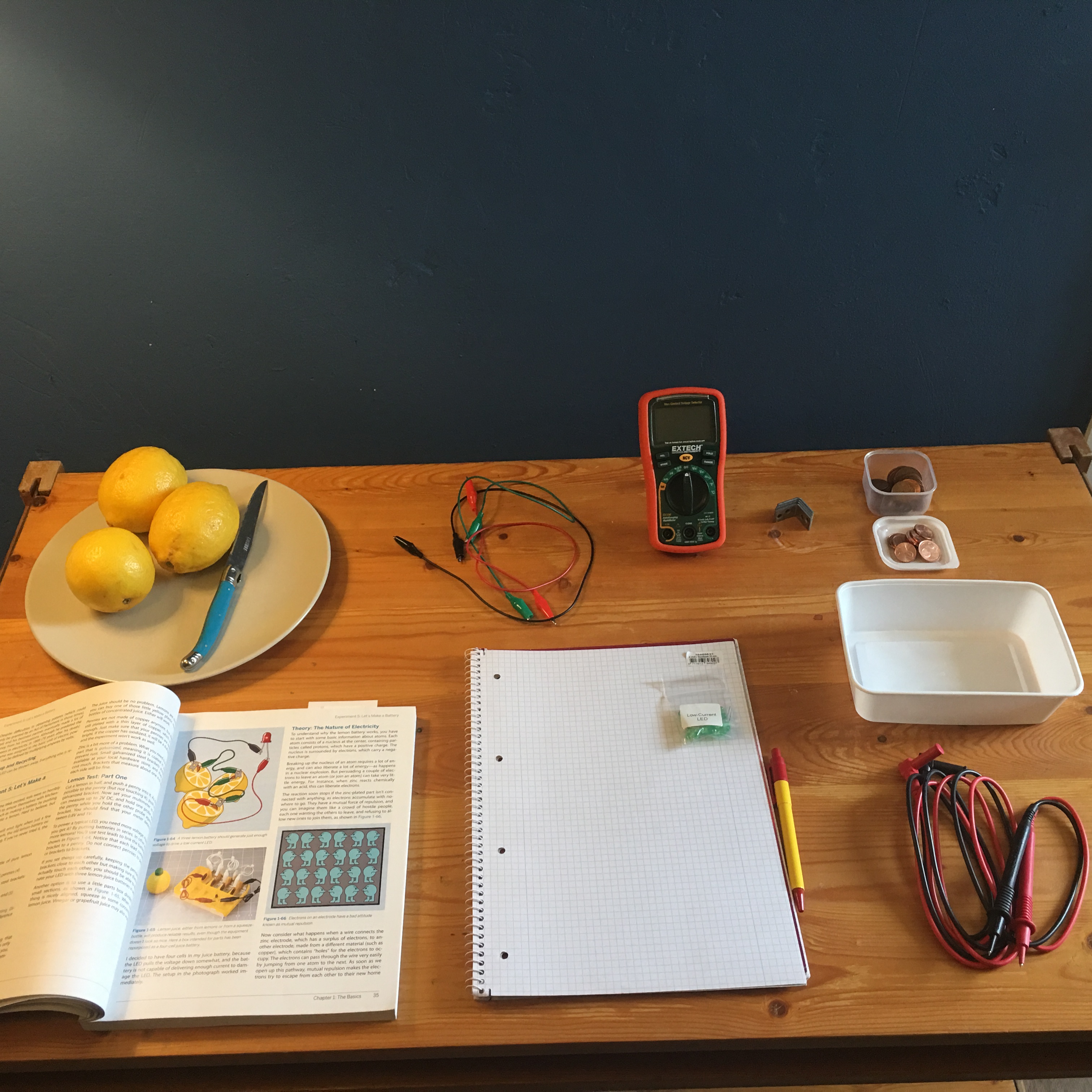
It’s time for the last experiment of Chapter 1


I found some really cheap L-shaped 1in. Zinc-plated steel brackets at my local hardware store.

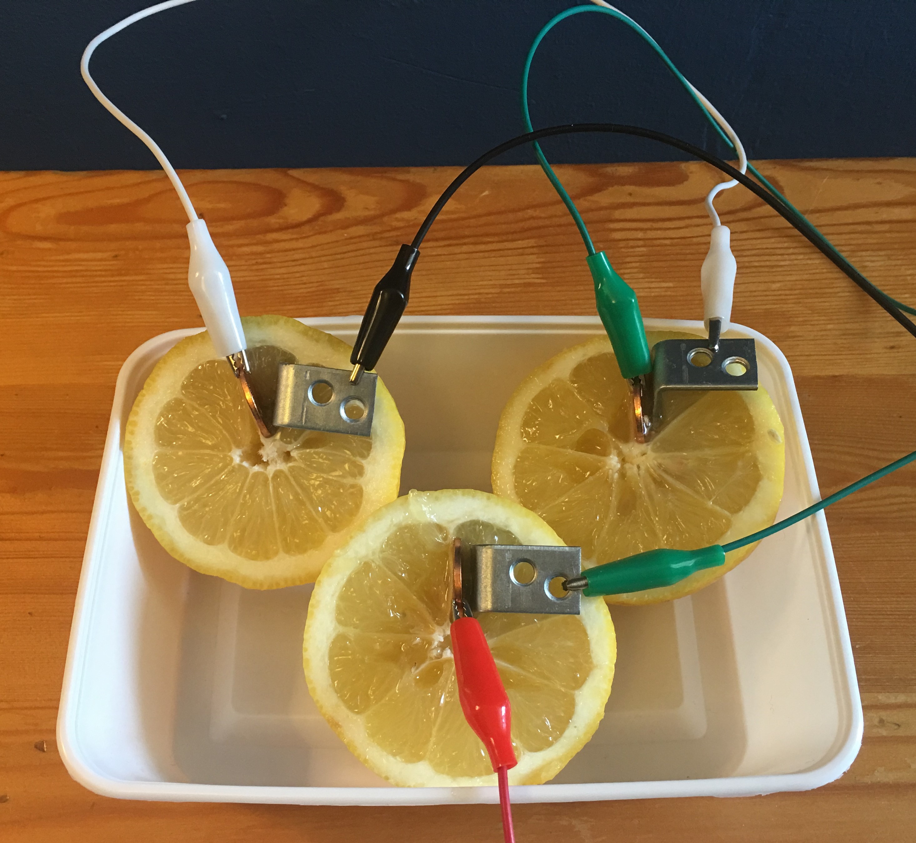
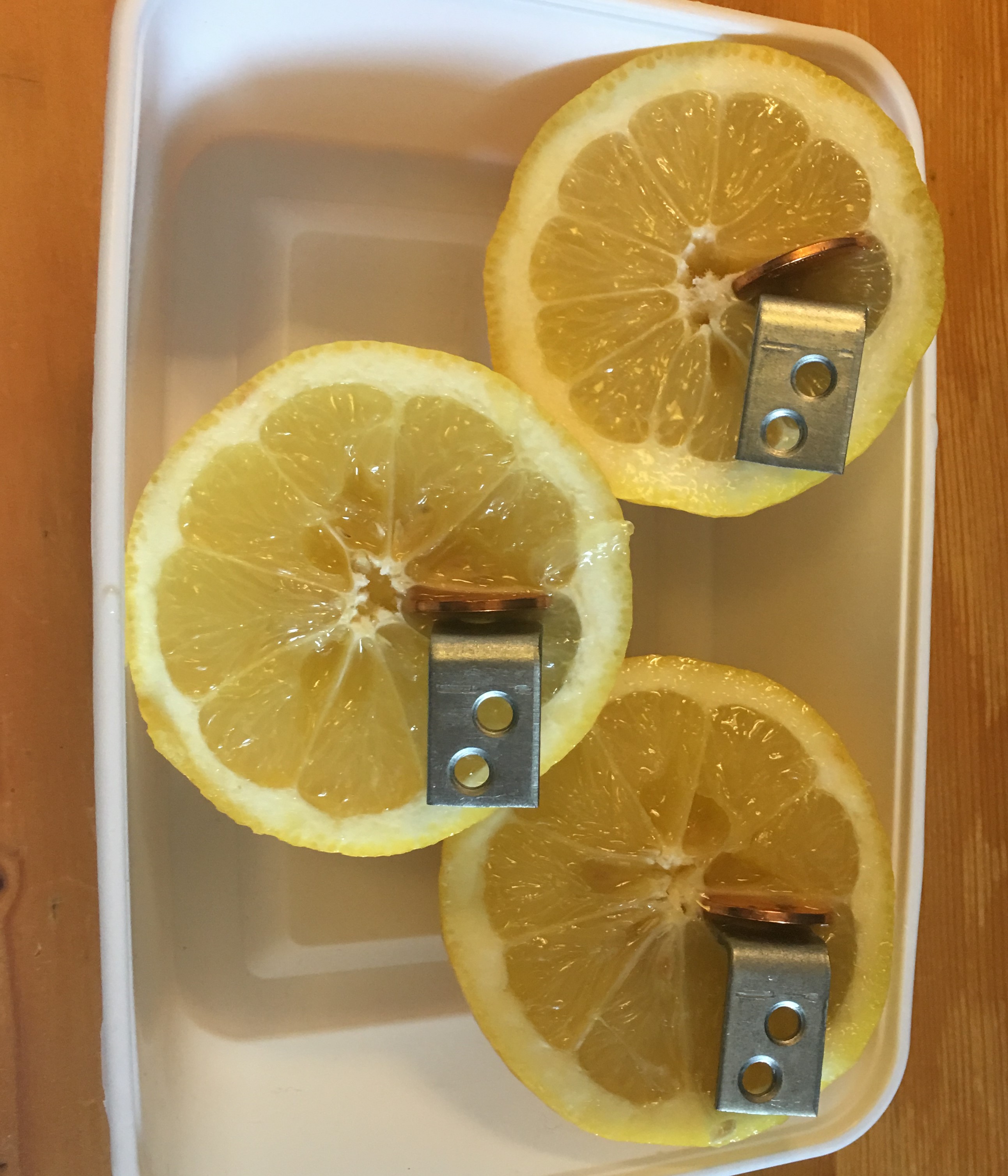
I was unable to light up the LED with this setup

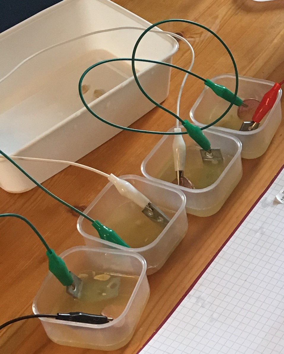
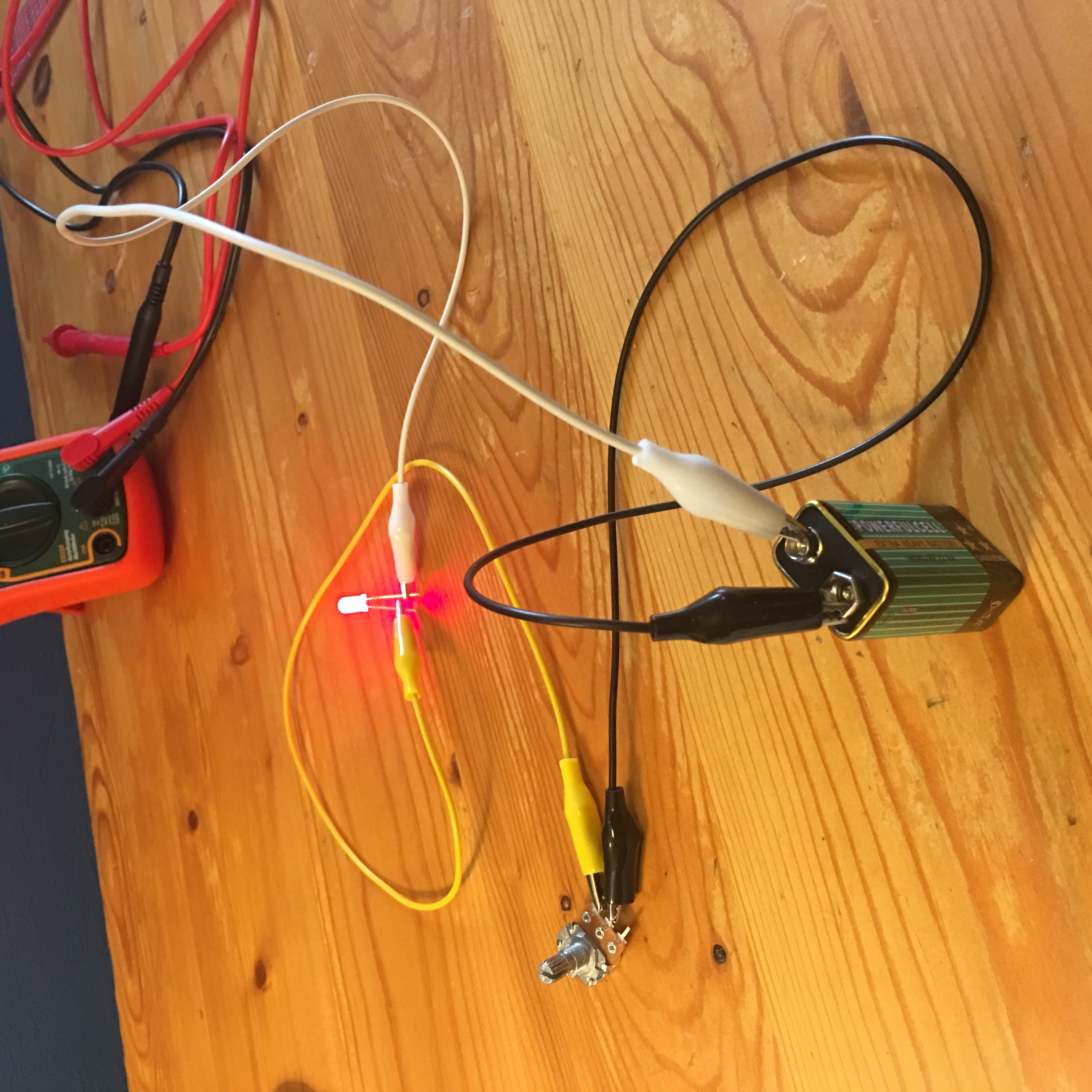
Luckily I found some small plastic containers at a dollar store and was able to imitate Mr. Platt’s second setup. This setup delivers more voltage since we’re connecting more pairs of electrodes (brackets and pennies) in series.

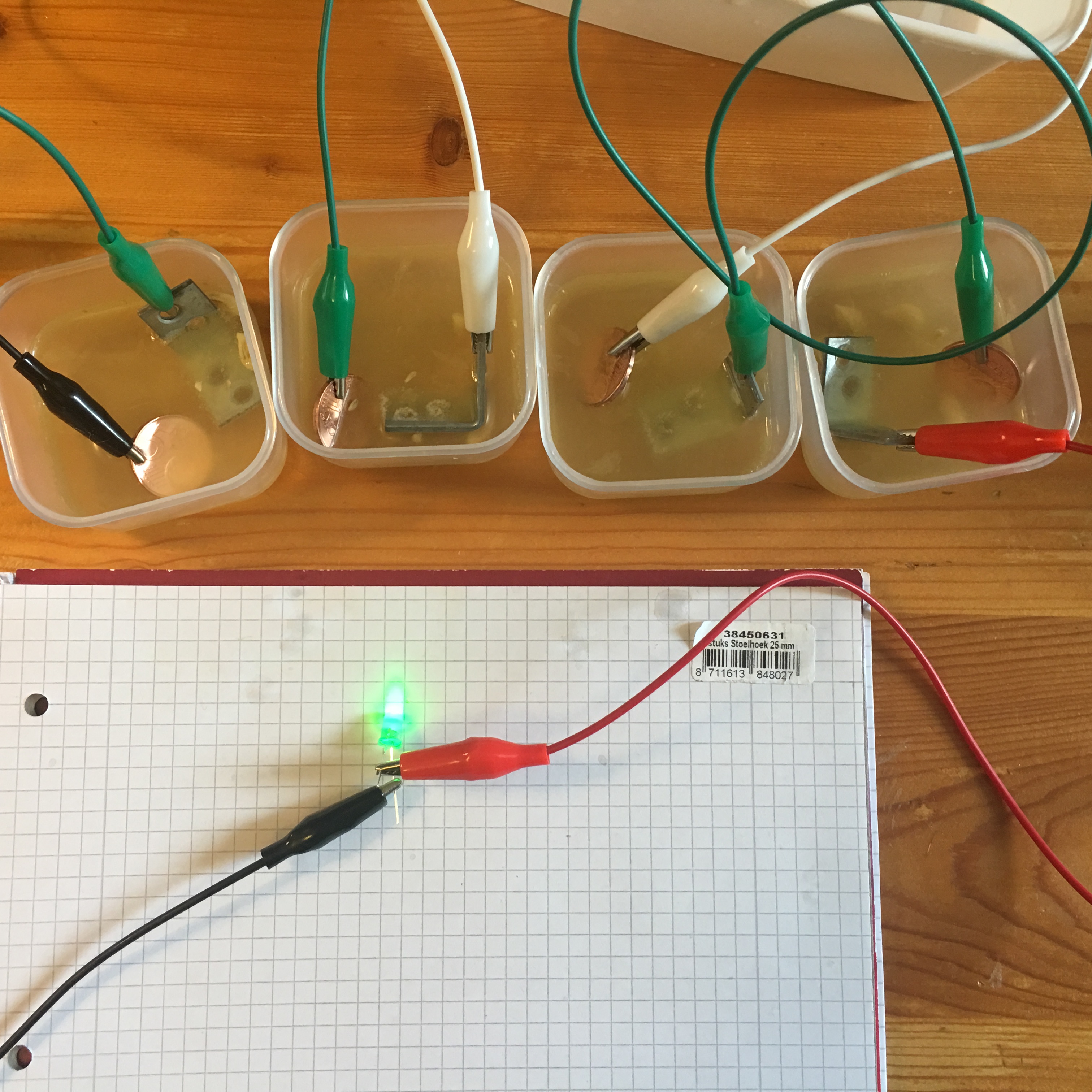
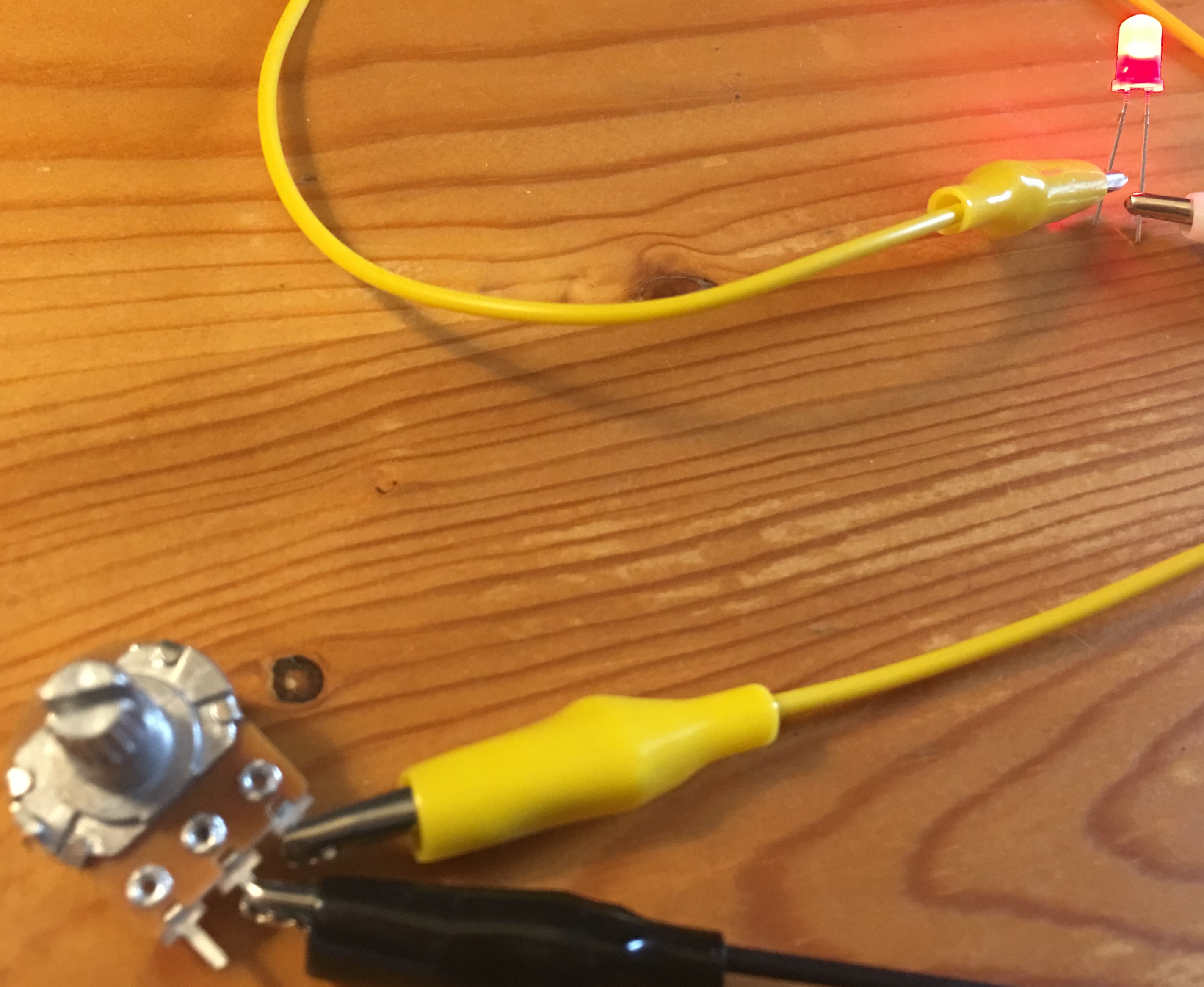
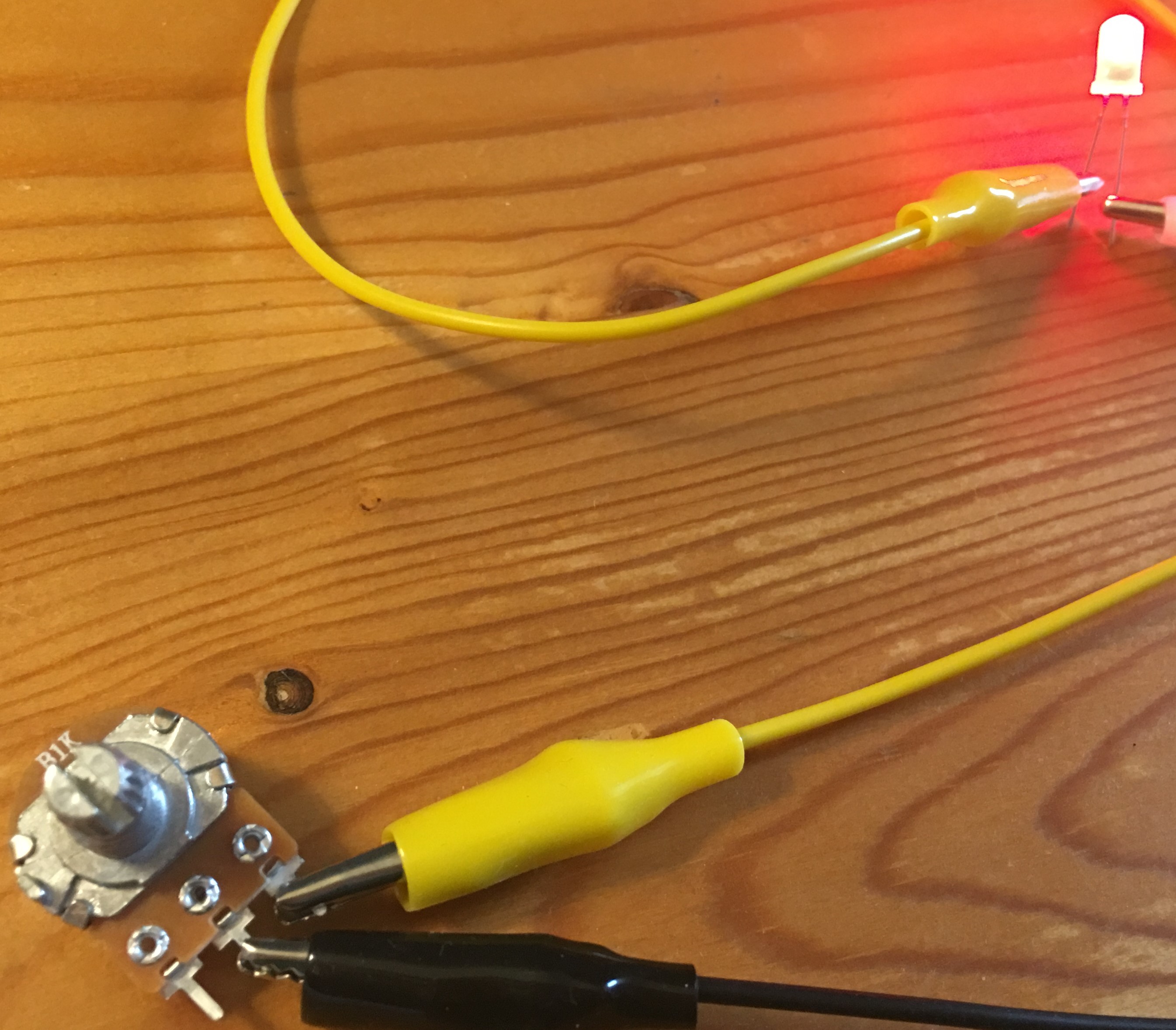
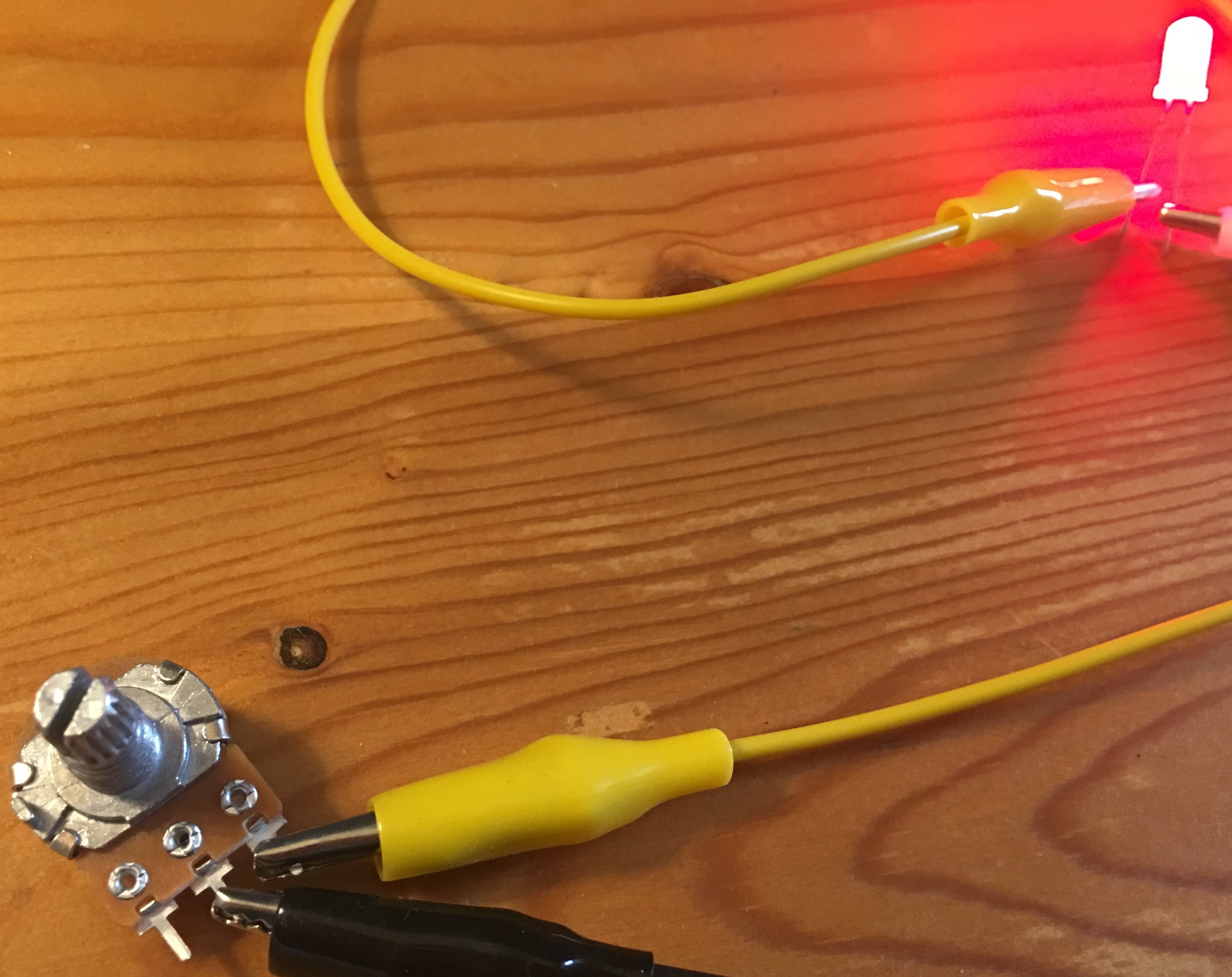
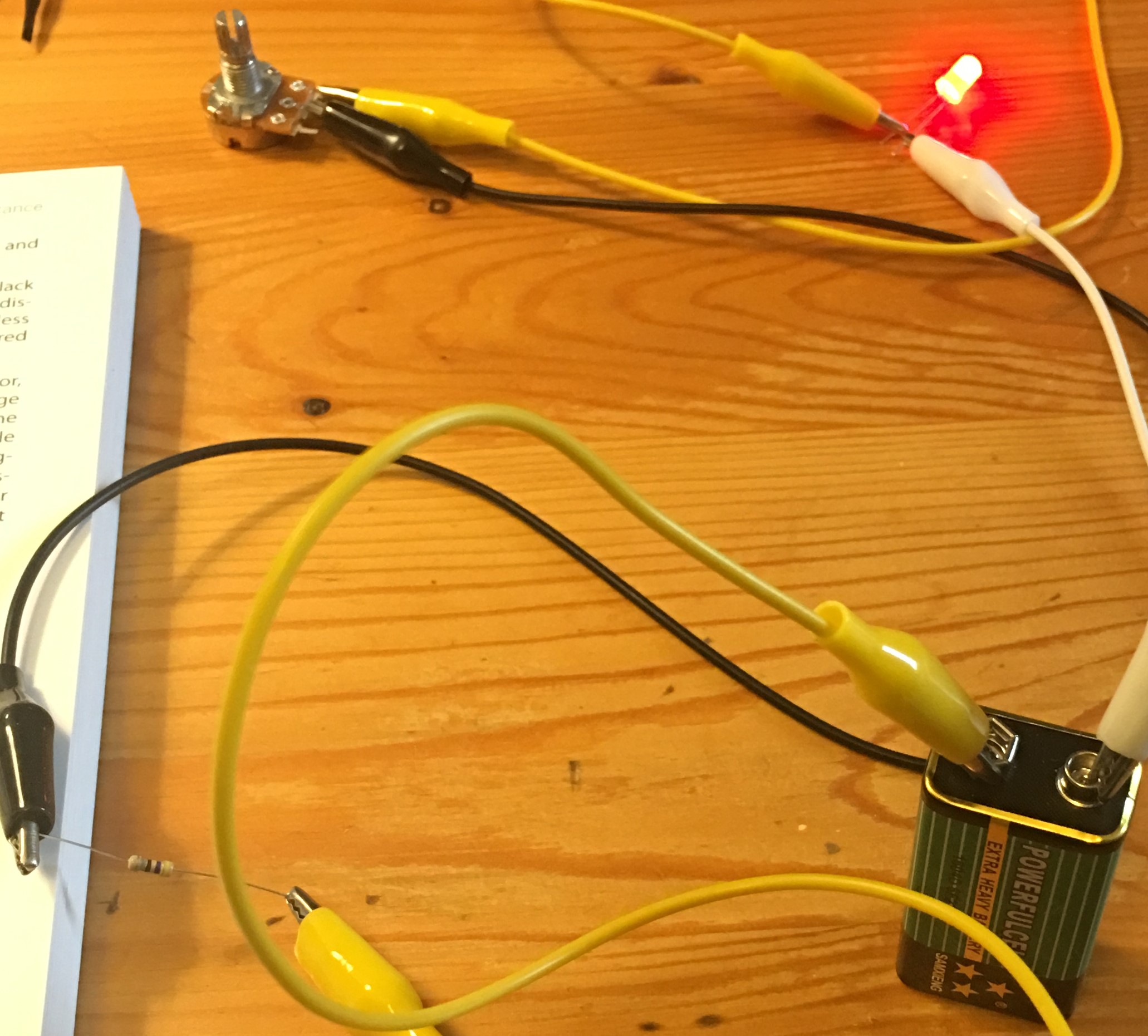
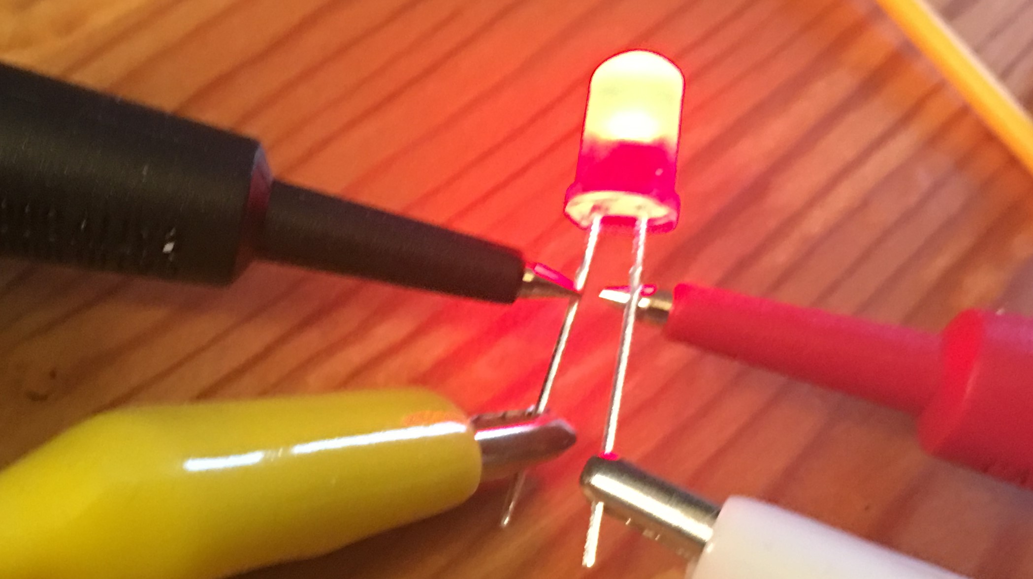
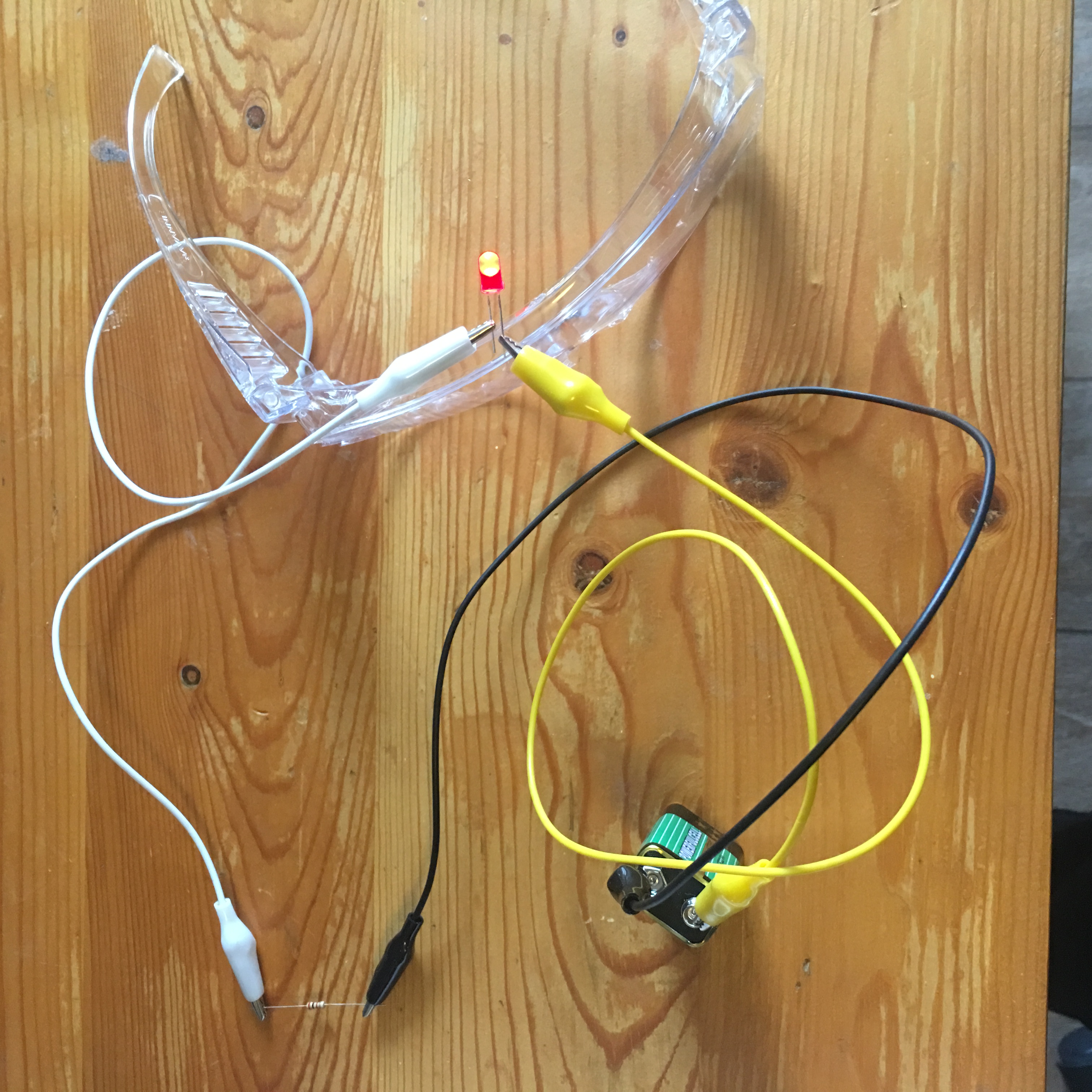
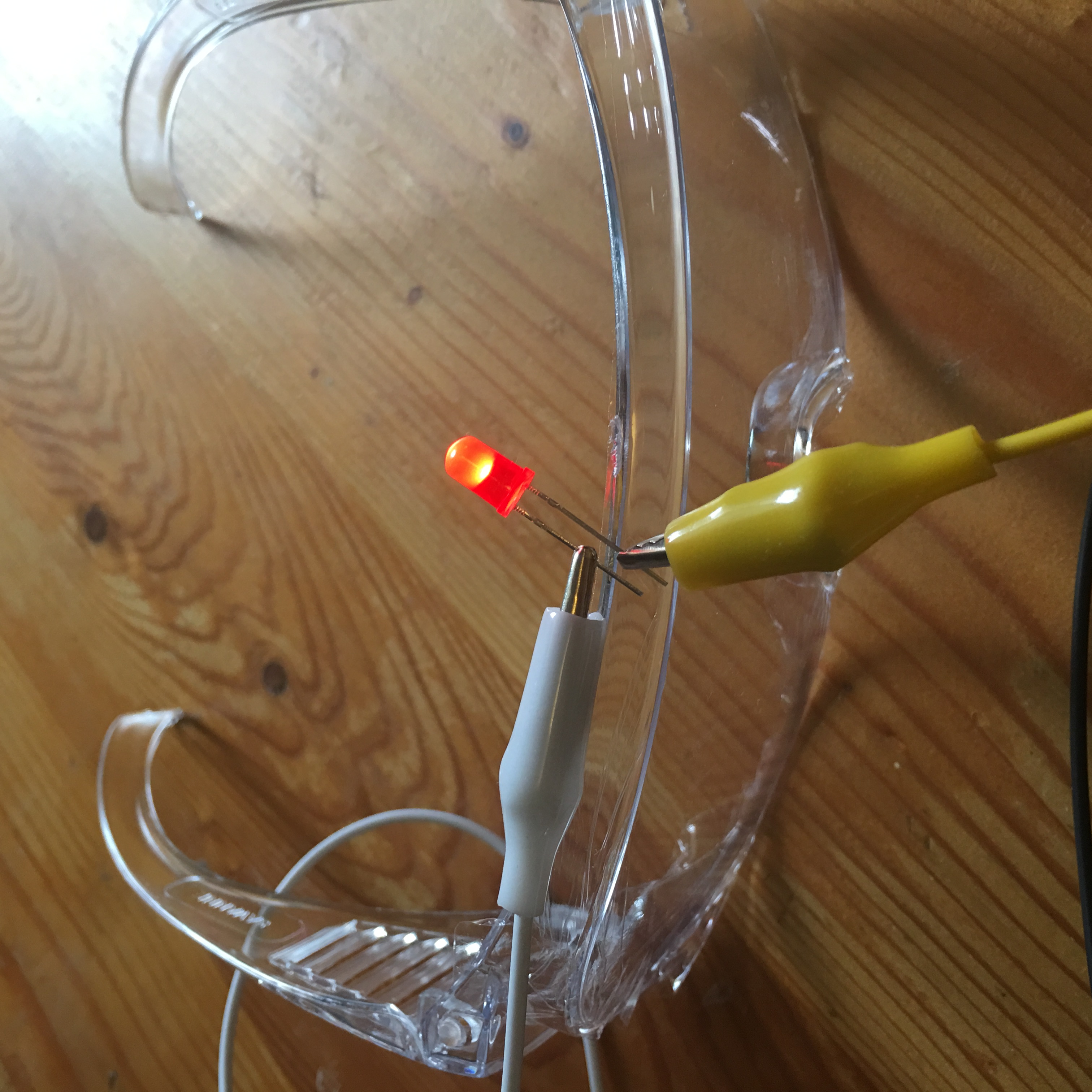
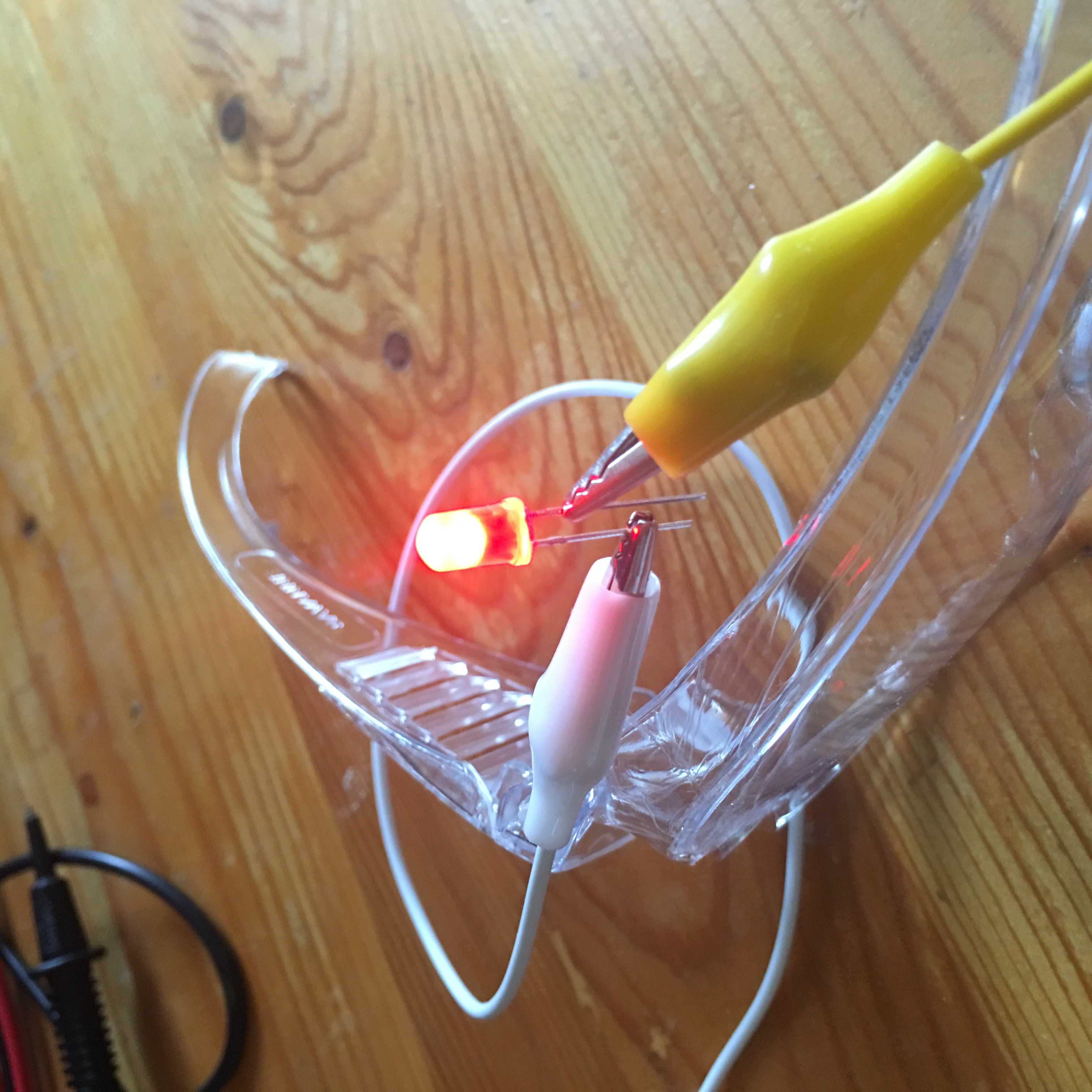
Shine bright like a LED!

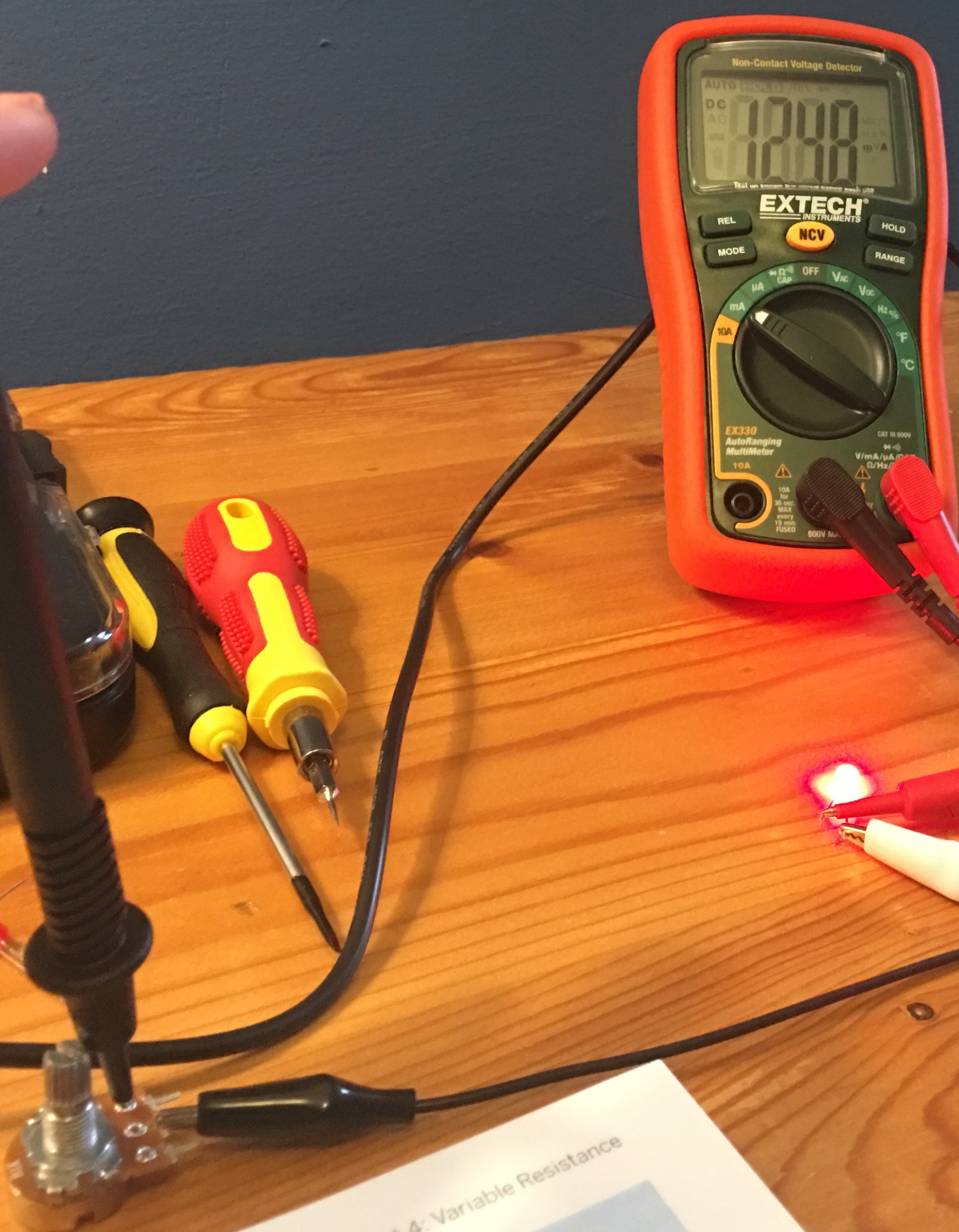
The highest voltage reading with this setup was 3.8V, which is higher than I was expecting. So be sure to measure the voltage of your circuit before connecting the LED to it. If the voltage measured is higher than the Max Forward voltage of your LED (check its datasheet), you could end up with another burnt LED like in experiment 4, or would you?

Turns out that while it is a bad idea to apply more than the recommended forward voltage to an LED, a lemon battery may be unable to sustain a voltage when it has a load applied to it (such as an LED). It would then be interesting to measure the voltage of the lemon battery with and without the LED attached (the voltage drops significantly when you add the LED).

The current is also important, the internal resistance of a battery limits current, and current is the main factor burning out an LED.

For these reasons, it’s safe to say you won’t end up with a burnt LED  when you connect it to our lemon battery!

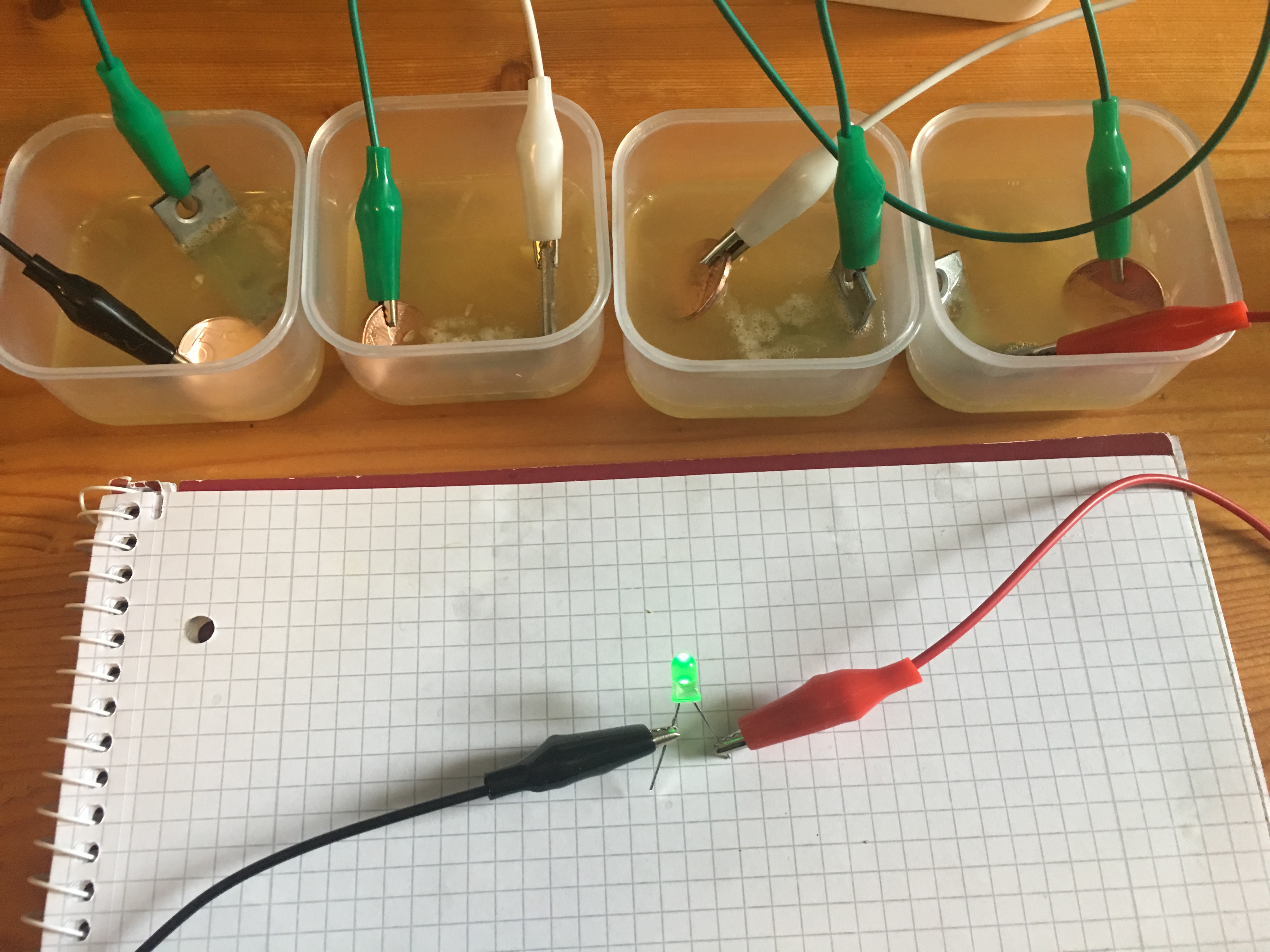
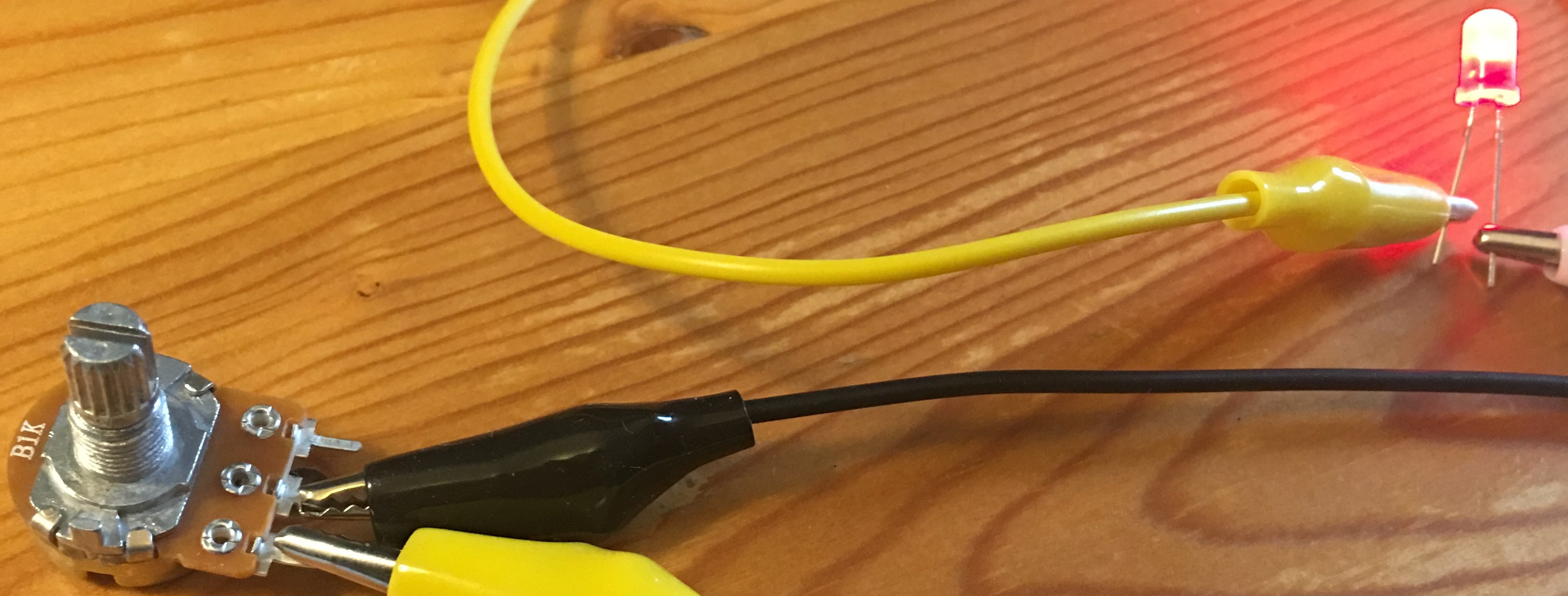
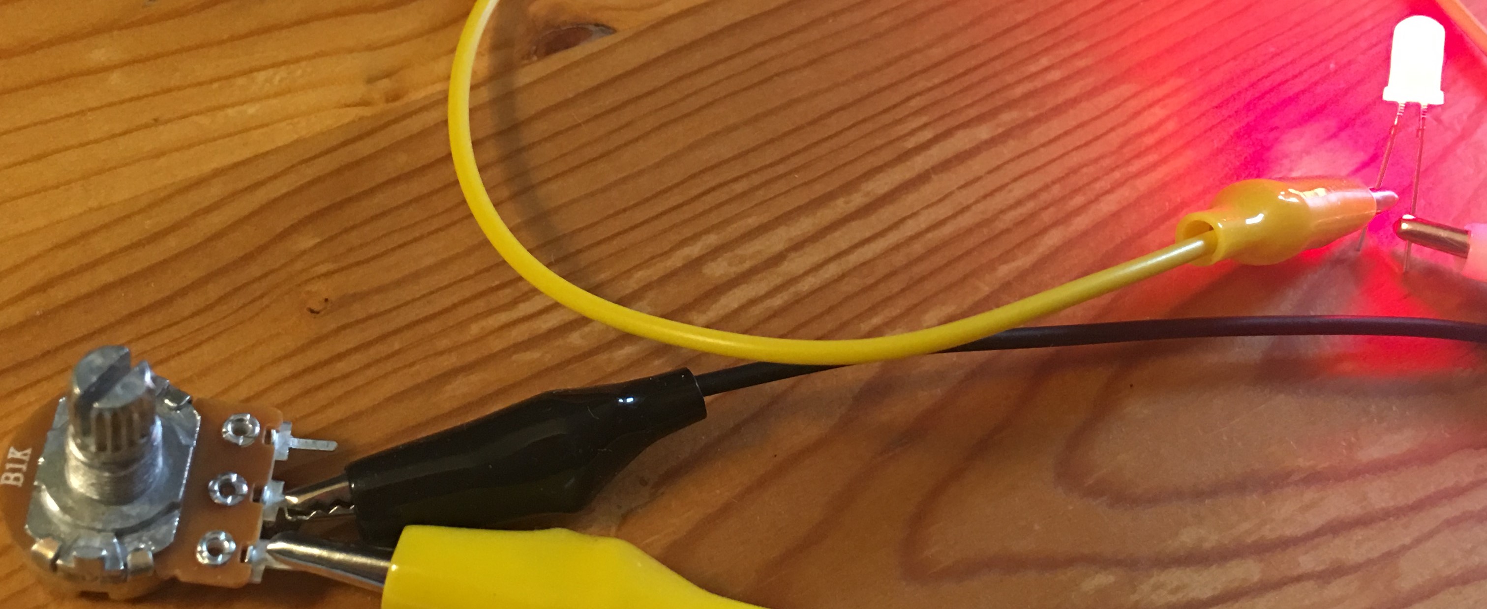
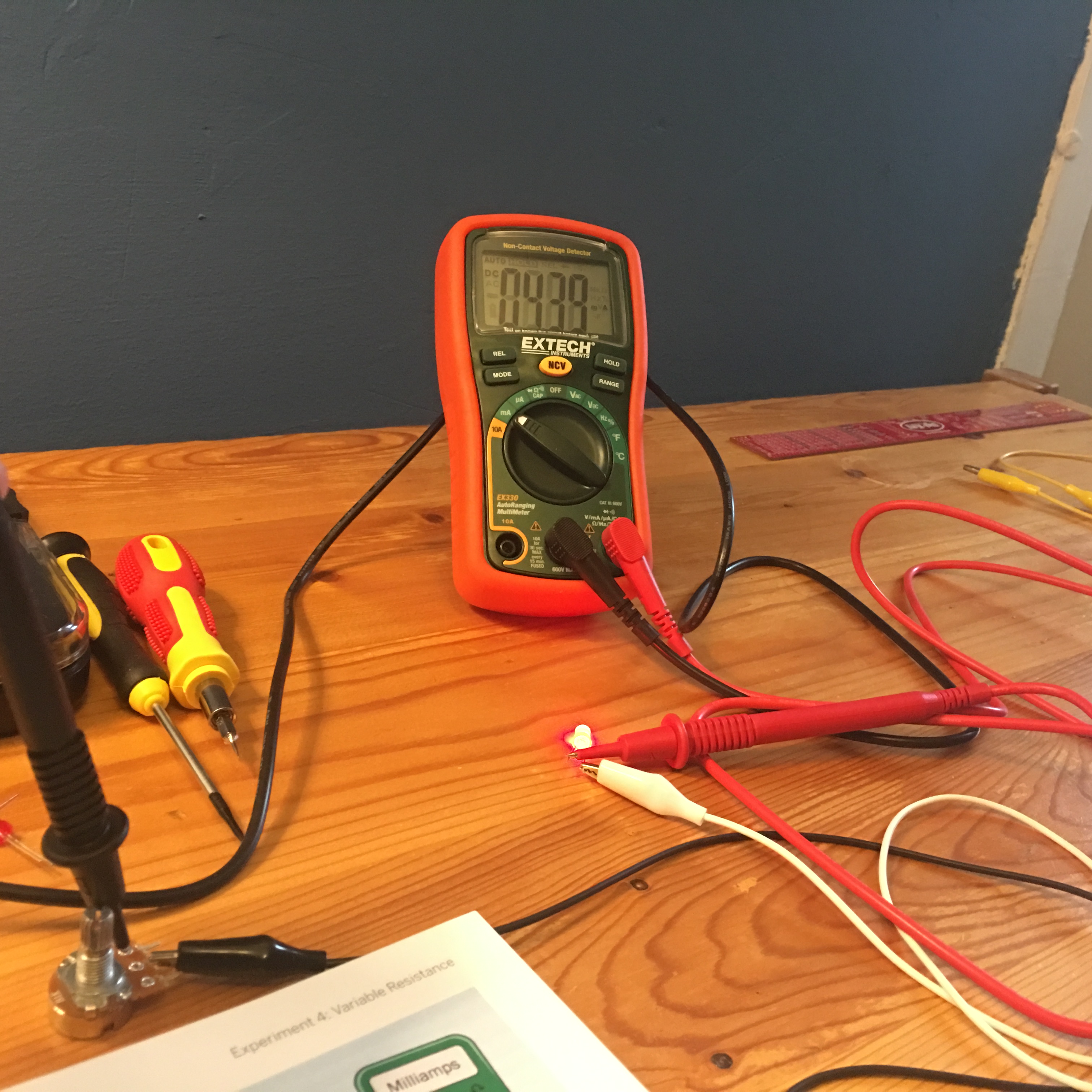
The Voltage eventually settled at 2.1V

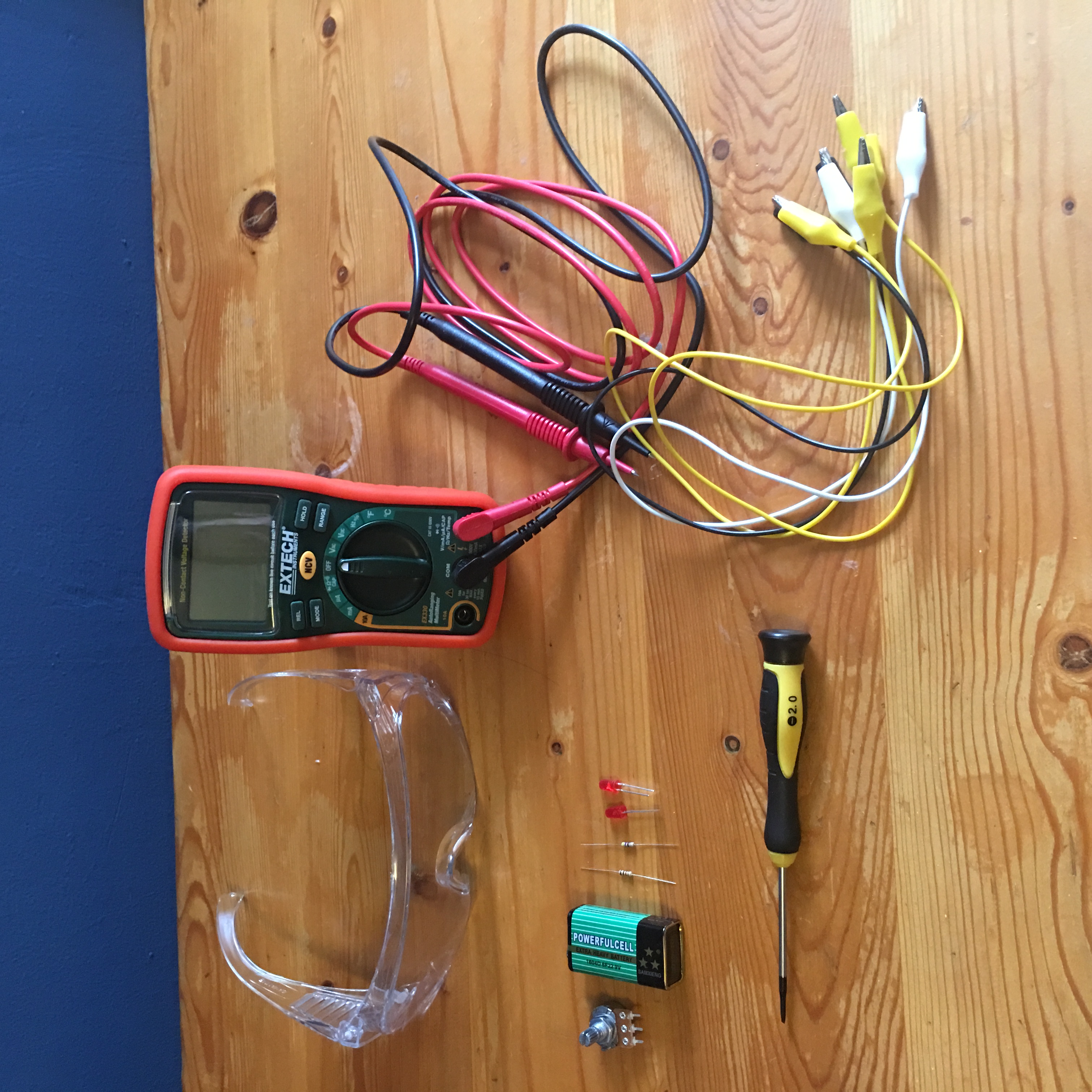
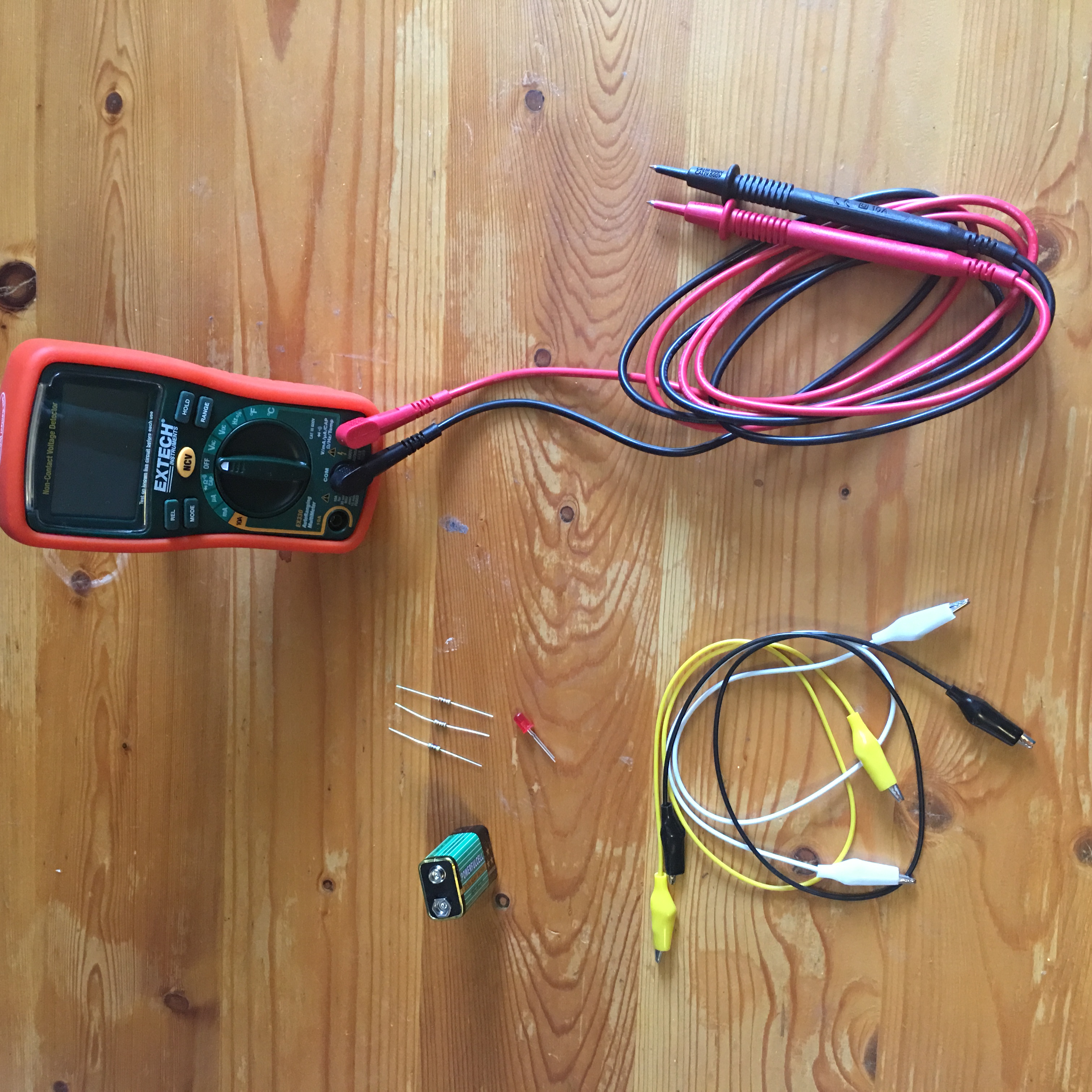
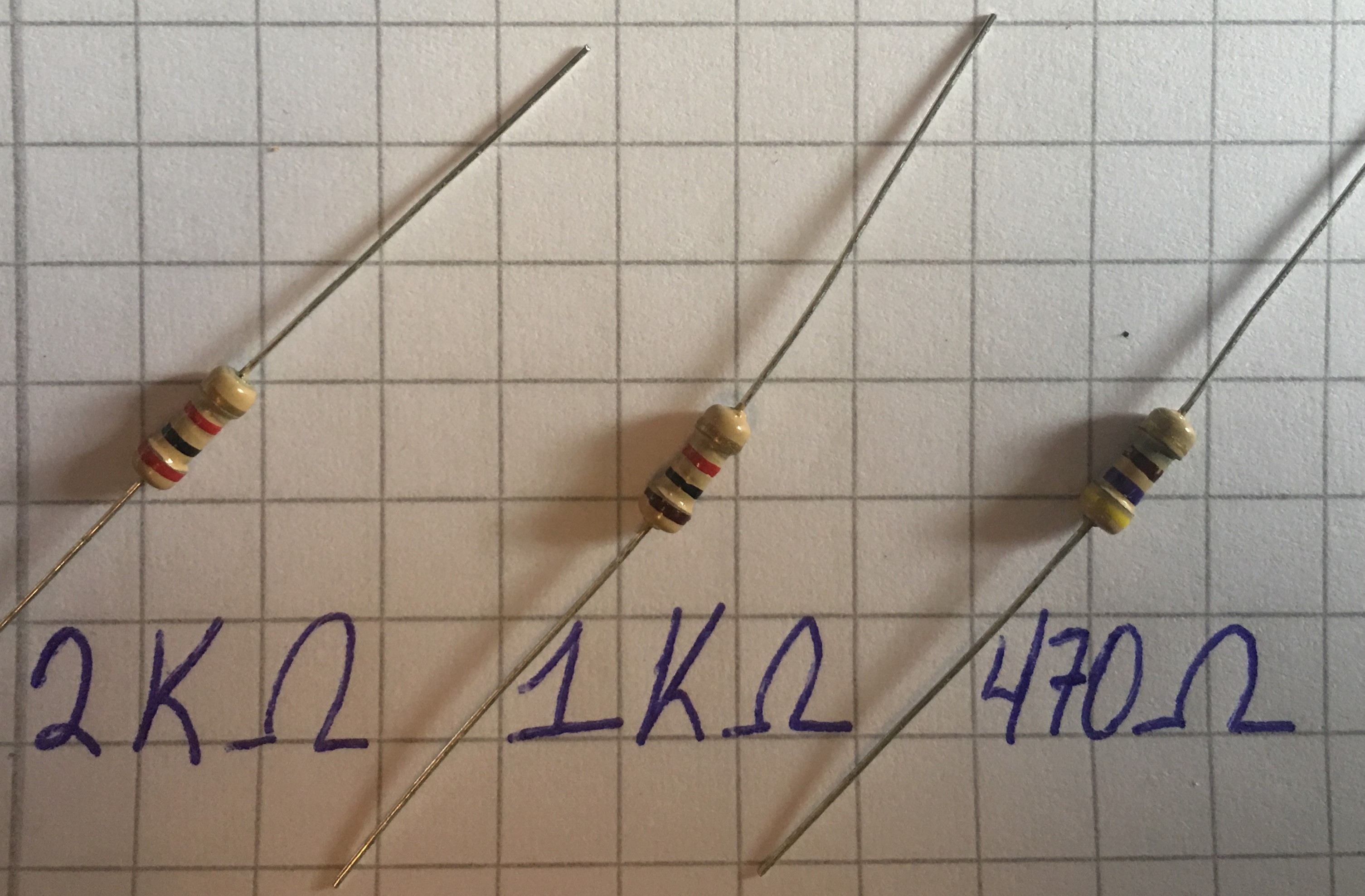
Be sure to carefully read through the theory section of this experiment. A basic understanding of the relationship between voltage, current, and resistance will greatly help your understanding of electricity and how and why circuits are formed.

To keep your test leads in good shape, clean them with soap and water then quickly dry them to avoid rusting.

Time for Chapter 2!


Experiment 4: Variable Resistance


* Look Inside Your Potentiometer

Here are some photos from different angles of the potentiometer I used (before prying it open):

Time to open it up!

* Testing the Potentiometer

Middle and Right terminals

Resistance

Min. Resistance (shaft fully turned clockwise)

2Ω

Max. Resistance (shaft fully turned counterclockwise)

1.036KΩ


* Dimming Your LED

The LED that wouldn’t die

I did NOT manage to burn the LED. I even connected it directly to the 9V battery but it just refused to burn.

Still, it was fun to play with the potentiometer, turning the knob and watching the LED’s brightness change as less and more current goes through it. A potentiometer isn’t polar so the LED would light up no matter which test lead was connected to which of the potentiometer’s terminals.


Center and Right terminals. As you turn the shaft clockwise, the LED shines brighter.

Center and Left terminals. As you turn the shaft counterclockwise, the LED shines brighter.

Protecting the LED with a resistor

* Measuring Potential Difference

Middle and Right terminals

Voltage

470Ω resistor

Voltage

1KΩ resistor

Min. Resistance (shaft fully turned clockwise)

24.4mV

13.5mV

Max. Resistance (shaft fully turned counterclockwise)

4.57V

3.530V

Measuring potential difference across an LED and a resistor

Middle and Right terminals

LED

470Ω resistor

Min. Resistance (shaft fully turned clockwise)

2mV

5.84V

Max. Resistance (shaft fully turned counterclockwise)

1.907V

2.049V


* Checking the Current

Multimeter between the LED and Potentiometer

Current

Min. Resistance (shaft fully turned clockwise)

12.48mA

Max. Resistance (shaft fully turned counterclockwise)

4.39mA


Multimeter between the battery and LED

Current

Min. Resistance (shaft fully turned clockwise)

12.30mA

Max. Resistance (shaft fully turned counterclockwise)

4.32mA


* Making Measurements

Multimeter between the potentiometer and battery (no LED)

Current

Min. Resistance (shaft fully turned clockwise)

8.50 mA

Medium Resistance (shaft turned halfway)

6.33mA

Max. Resistance (shaft fully turned counterclockwise)

4.25mA


* Fundamentals: Series and Parallel

Two resistors in parallel (R1= 470Ω, R2= 1KΩ) offer an equivalent resistance of 319.73Ω

Of course, the measurements won’t always be what we expect, this due to the fact that each component has a tolerance range, so, for example, a 1K resistor with a 5% tolerance may offer a resistance that is 5% away from 1K. The reading my multimeter gave of the two resistors in parallel shown in the picture above was 318.8Ω.


Experiment 3: Your First Circuit

It’s time, people, time to light up some LEDs!!!

* Lighting an LED

So, the thing is, I didn’t have a 2.2KΩ resistor at hand, as you can see in the picture above, (now that you know how to decode the value of resistors from the Fundamentals: Decoding Resistors section).

My resistor is Red Black Red Gold = 2 0 2 5% = 2000 Ohms with a 5% tolerance.

A 2.2K (2000) resistor would show the colors Red Red Red Gold = 2 2 2 5% = 2200Ω, 5% tolerance.

Still, the Resistor is still perfectly usable for the educational lesson the experiment wishes to transmit, which is: How does resistance affect current?

Here are the other resistors that will be tested:


So, let’s begin!

It’s alive!!!…..ever so slightly.

Circuit with a 2KΩ resistor                               Circuit with a 1KΩ resistor   

 Circuit with a 470Ω resistor


As the resistance is decreased (by changing the resistor) the LED shines more brightly since more current is going through it!


* Checking a Resistor

These are the values the color coding of each resistor translates into.

The first resistor is 2KΩ (and not 2.2kΩ). The multi-meter shows a value of 1.993KΩ which is within the tolerance specified by the golden stripe (5%).